sh030051g.pdf - 第348页
13 - 47 13. SERVO AMPLIFIERS WI TH A LARGE CAPACITY ( 30k TO 55kW ) 13.3.8 Servo motor side details Terminal box Enco der co nnect or CM10-R10P Encoder connector signal arrangement CM10-R10P 5 6 1 4 3 2 8 7 9 10 Terminal…
13 - 46
13. SERVO AMPLIFIERS WITH A LARGE CAPACITY
(
30k TO 55kW
)
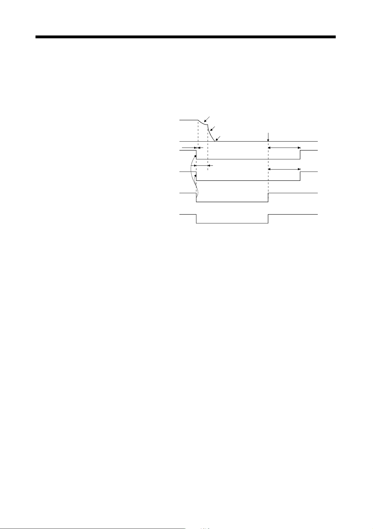
(b) Forced stop in the drive unit
When the forced stop (EM1) is made valid in the drive unit, the drive unit in operation stops, Main circuit
off warning (E9) appears, and then the drive unit is forcedly stopped. Configure to activate the forced
stop (EM1) of the drive unit as the forced stop (EM1) of the converter unit is activated, and to activate
the forced stop (EM1) of the converter unit as the forced stop (EM1) of the drive unit is activated. Shut
off the power supply by the external sequence as soon as the forced stop (EM1) is activated.
Electromagnetic brake
interlock (MBR)
(10ms)
(3s)
(3s)
Invalid (ON)
Valid (OFF)
Base circuit
ON
OFF
Servo motor speed
Forced stop command
(from controller) or
forced stop (EM1)
ON
OFF
Main circuit
power supply
ON
OFF
Dynamic brake
Dynamic brake
Electromagnetic brake
Electromagnetic brake
Electromagnetic brake
operation delay time
Electromagnetic brake release
(Note)
Note. ON: Electromagnetic brake is not activated.
OFF: Electromagnetic brake is activated
13 - 47
13. SERVO AMPLIFIERS WITH A LARGE CAPACITY
(
30k TO 55kW
)
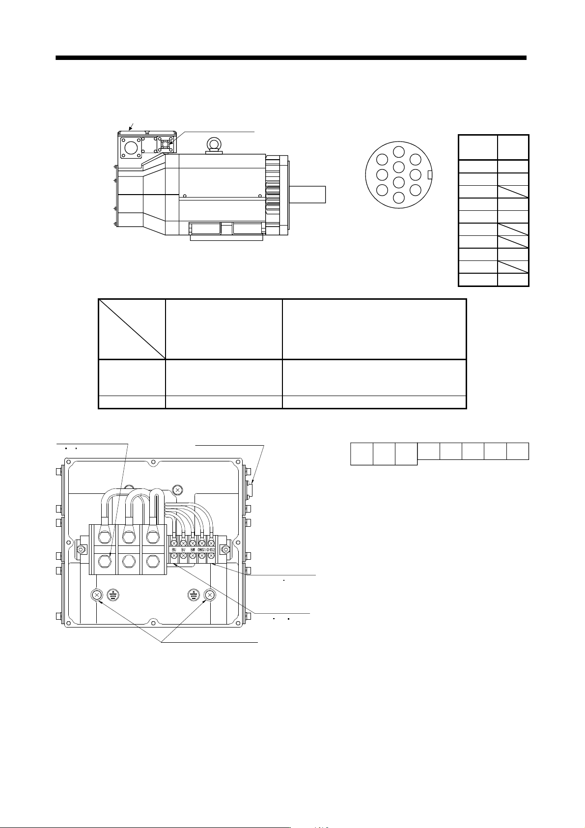
13.3.8 Servo motor side details
Terminal box
Encoder connector
CM10-R10P
Encoder connector signal arrangement
CM10-R10P
5
6
1
4
3
2
8
7
9
10
Terminal
No.
Signal
1 MR
2 MRR
3
4 BAT
5 LG
6
7
8 P5
9
10 SHD
HA-LP30K1M4 HA-LP30K24
HA-LP37K24
HA-LP30K1
HA-LP37K1
HA-LP30K1M
HA-LP37K1M
HA-LP30K2
HA-LP37K2
HA-LP25K14
HA-LP30K14
HA-LP37K14
HA-LP37K1M4
HA-LP45K1M4
HA-LP50K1M4
HA-LP45K24
HA-LP55K24
Motor power
supply terminal
block screw size
M8 M10
Earth screw size M6 M6
CM10-R10P
Encoder connector
U
V
W
Earth terminal M6 screw
Motor power supply
terminal block
(U V W) M8 screw
Cooling fan
terminal block
(BU BV BW)
M4 screw
Thermal sensor
terminal block
(OHS1 OHS2)
M4 screw
UVW
BU BV BW OHS1OHS2
Terminal block signal arrangement
13 - 48
13. SERVO AMPLIFIERS WITH A LARGE CAPACITY
(
30k TO 55kW
)
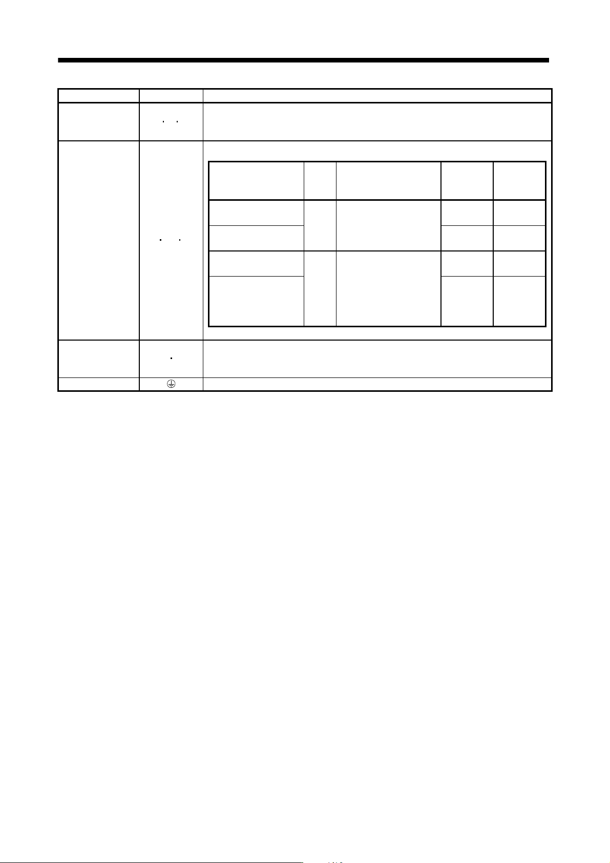
Signal name Abbreviation Description
Servo motor
power supply
U
V W
Connect to the motor power terminals (U, V, W) of the drive unit. During power-on, do not
open or close the motor power line.
Otherwise, a malfunction or faulty may occur.
Cooling fan BU BV BW
Supply power which satisfies the following specifications.
Servo motor
Voltage
division
Voltage/
frequency
Power
consumption
[W]
Rated
current
[A]
HA-LP30K1M, 30K2,
37K2
200V
class
3-phase 200 to 230VAC
50Hz/60Hz
65(50Hz)
85(60Hz)
0.20(50Hz)
0.22(60Hz)
HA-LP30K1, 37K1,
37K1M
120(50Hz)
175(60Hz)
0.65(50Hz)
0.80(60Hz)
HA-LP30K1M4,
30K24, 37K24
400V
class
3-phase 380 to 460VAC
50Hz
3-phase 380 to 480VAC
60Hz
65(50Hz)
85(60Hz)
0.12(50Hz)
0.14(60Hz)
HA-LP30K14, 37K14,
37K1M4, 45K1M4,
50K1M4, 45K24,
55K24
110(50Hz)
150(60Hz)
0.20(50Hz)
0.22(60Hz)
Motor thermal relay OHS1 OHS2
OHS1-OHS2 are opened when heat is generated to an abnormal temperature.
Maximum rating: 125V AC/DC, 3A or 250V AC/DC, 2A
Minimum rating: 6V AC/DC, 0.15A
Earth terminal For grounding, connect to the earth of the control box via the earth terminal of the drive unit.