sh030051g.pdf - 第353页
13 - 52 13. SERVO AMPLIFIERS WI TH A LARGE CAPACITY ( 30k TO 55kW ) (b) Display definition The 7-segment LED segments and CN1 connector pins correspond as shown below. Lit: ON Extin guished : OFF Input signals Output s i…
13 - 51
13. SERVO AMPLIFIERS WITH A LARGE CAPACITY
(
30k TO 55kW
)
13.4.3 Diagnostic mode
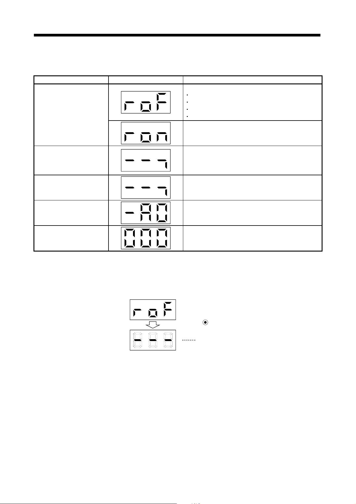
(1) Diagnostic list
Name Display Unit
Sequence
Not ready.
Initializing.
An alarm occurred.
External forced stop status.
Bus voltage is not established.
Ready
Indicates that the servo was switched on after completion of
initialization and the drive unit is ready to operate.
External I/O signal display
Indicates the ON/OFF status of external I/O signal.
Lit : ON
Extinguished: OFF
For details, refer to (2) of this section.
Output signal forced output
Allows external I/O signal to be switched on/off forcibly. For
details, refer to (3) of this section.
Software version low
Indicates the version of the software.
Software version high
Indicates the system number of the software.
(2) External I/O signal display
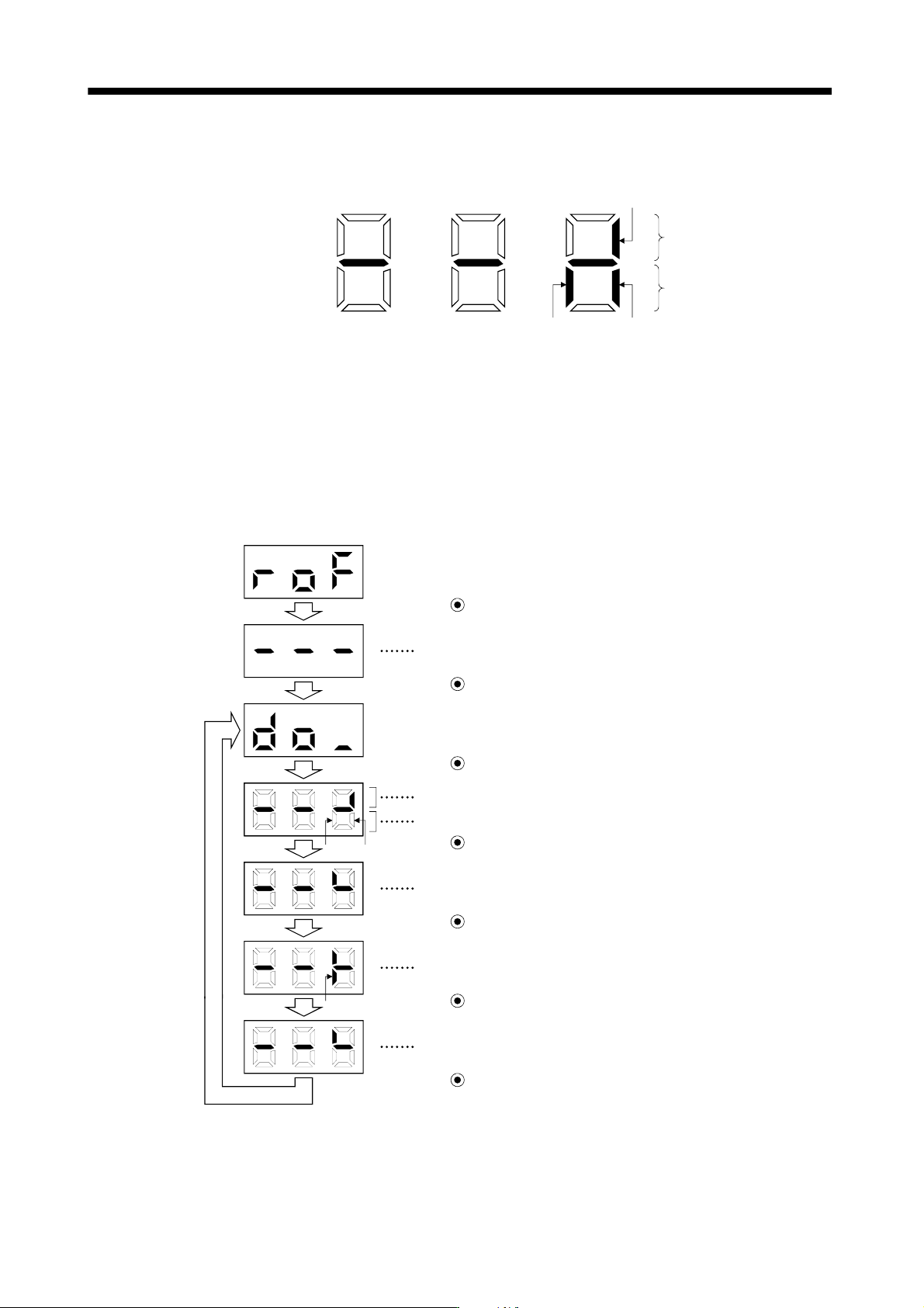
The ON/OFF states of the digital I/O signals connected to the converter unit can be confirmed.
(a) Operation
Call the display screen shown after power-on. Using the "MODE" button, show the diagnostic screen.
External I/O signal display screen
Press MODE once.
13 - 52
13. SERVO AMPLIFIERS WITH A LARGE CAPACITY
(
30k TO 55kW
)
(b) Display definition
The 7-segment LED segments and CN1 connector pins correspond as shown below.
Lit: ON
Extinguished: OFF
Input signals
Output signals
CN1-7: Forced stop (EM1)
CN1-8:
Warning (WNG)
CN-2:
Trouble (ALM)
The LED segment corresponding to the pin is lit to indicate ON, and is extinguished to indicate OFF.
(3) Output signal forced output
You can force the output signal to be switched on/off, independently of the converter status.
This function is used for wiring check of output signal.
When turning CN1-8 on and off
External I/O signal display screen
Press SET for more than 2 seconds.
CN1-8
CN1-8 CN1-2
Press MODE once.
Press UP once.
The signal under the lit LED is switched on/off.
Indicates ON/OFF of the trouble (ALM) signal. (Lit: ON, extinguished: OFF)
Press MODE once.
The lit LED moves to the upper LED of CN1-8.
Press UP once.
CN1-8 switches on. (WNG-DOCOM are connected.)
Press DOWN once.
CN1-8 switches off.
Press SET for more than 2 seconds.
Call the display screen shown after power-on.
13 - 53
13. SERVO AMPLIFIERS WITH A LARGE CAPACITY
(
30k TO 55kW
)
13.4.4 Alarm mode
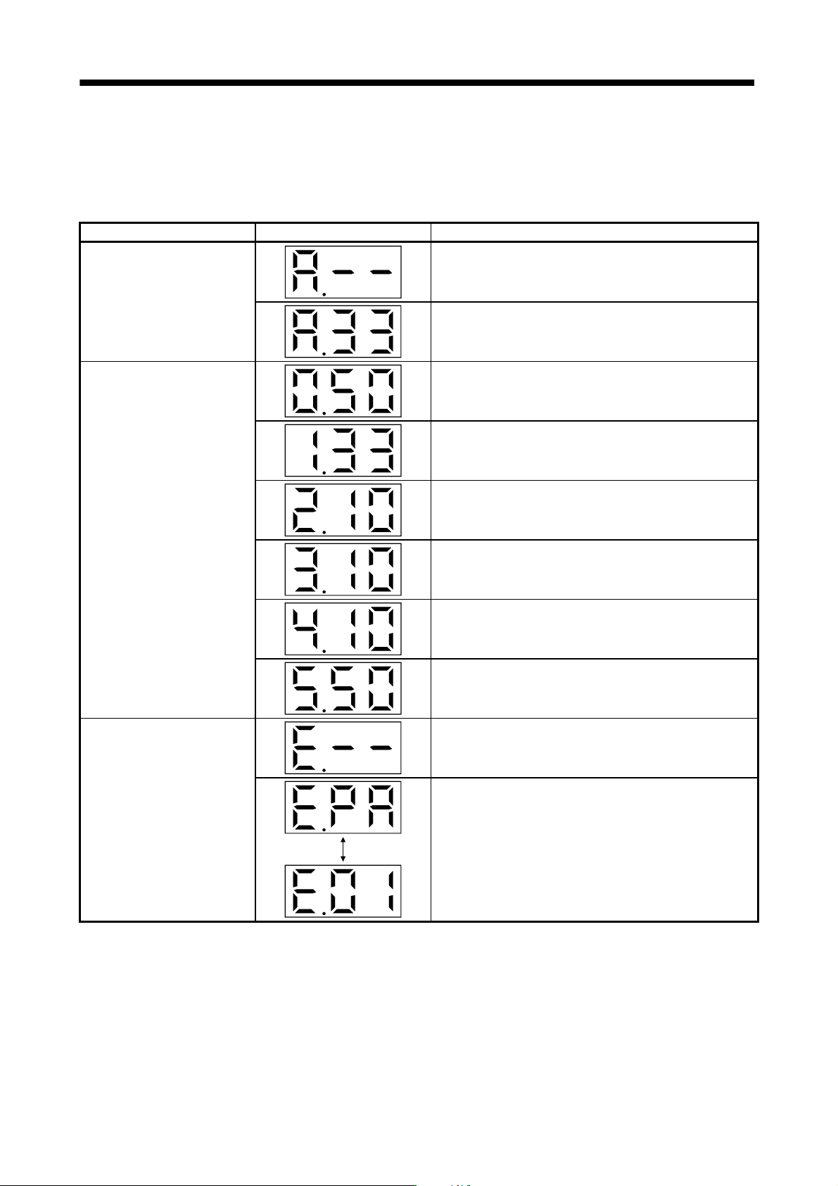
The current alarm, parameter error and point table error are displayed.
The lower 2 digits on the display indicate the alarm number that has occurred or the parameter number in error.
Display example are shown below.
Name Display Description
Current alarm
Indicates on occurrence of an alarm.
Indicates that overvoltage (A.33) occurred.
Flickers at alarm occurrence.
Indicates that the last alarm is overload (A.50).
Indicates that the second alarm in the past is overvoltage
(A.33).
Alarm history
Indicates that the third alarm in the past is undervoltage (A.10).
Indicates that the fourth alarm in the past is undervoltage
(A.10).
Indicates that the fifth alarm in the past is undervoltage (A.10).
Indicates that the sixth alarm in the past is overload (A.50).
Parameter error No.
Indicates no occurrence of parameter error (A.37).
Displayed
alternately
Indicates that the data of parameter No.PA01 is faulty.