sh030051g.pdf - 第107页
3 - 52 3. SIGNALS AND WI RING 3.13 Control axis selection POINT The control axis number set to rotary axis setting switch (SW1) sh ould be the same as the one set to the servo system controlle r. Use the rotary axis sett…
3 - 51
3. SIGNALS AND WIRING
3.12 Grounding
WARNING
Ground the servo amplifier and servo motor securely.
To prevent an electric shock, always connect the protective earth (PE) terminal
(terminal marked
) of the servo amplifier with the protective earth (PE) of the
control box.
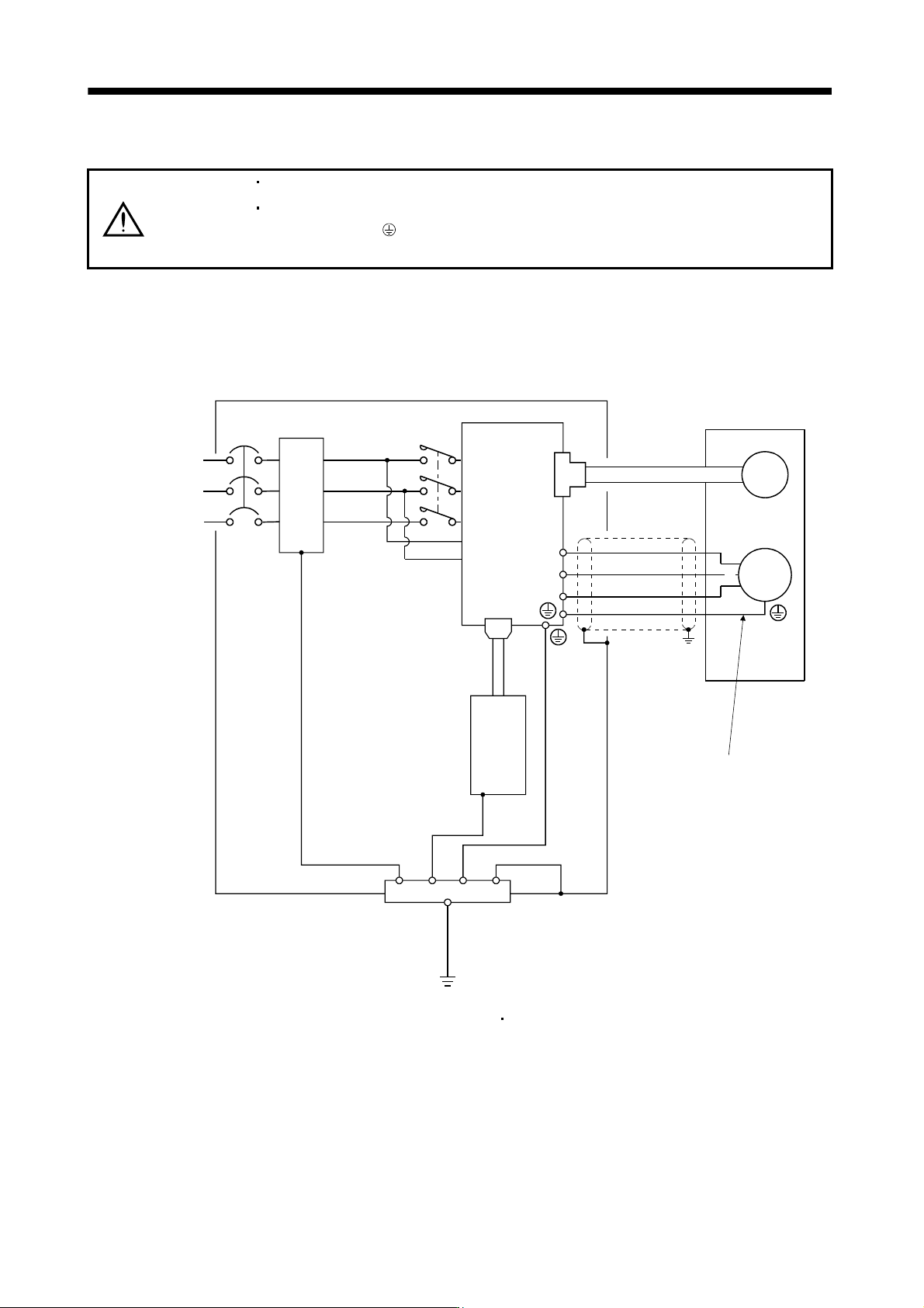
The servo amplifier switches the power transistor on-off to supply power to the servo motor. Depending on the
wiring and ground cable routing, the servo amplifier may be affected by the switching noise (due to di/dt and
dv/dt) of the transistor. To prevent such a fault, refer to the following diagram and always ground.
To conform to the EMC Directive, refer to the EMC Installation Guidelines (IB(NA)67310).
L
1
L2
L
3
L11
L21
CN1A
NFB
MC
CN2
U
V
W
M
U
V
W
Control box
Servo amplifier
Line filter
Protective earth(PE)
Outer
box
Servo motor
Encoder
(Note)
Power supply
Servo system
controller
Ensure to connect it to PE
terminal of the servo amplifier.
Do not connect it directly
to the protective earth of
the control panel.
Note. For 1-phase 200V to 230VAC, connect the power supply to L1 L2 and leave L3 open.
There is no L
3 for 1-phase 100 to 120VAC power supply. Refer to section 1.3 for the power supply specification.
3 - 52
3. SIGNALS AND WIRING
3.13 Control axis selection
POINT
The control axis number set to rotary axis setting switch (SW1) should be the
same as the one set to the servo system controller.
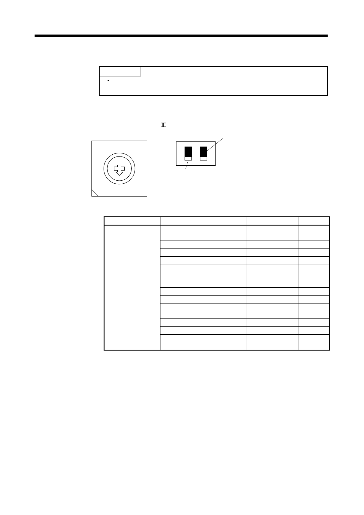
Use the rotary axis setting switch (SW1) to set the control axis number for the servo. If the same numbers are
set to different control axes in a single communication system, the system will not operate properly. The control
axes may be set independently of the SSCNET
cable connection sequence.
8
7
6
5
4
3
2
1
0
F
E
D
C
B
A
9
Rotary axis setting switch (SW1)
Down
Up
Test operation select switch (SW2-1)
Set the test operation select switch to the "Up" position, when
performing the test operation mode by using MR Configurator.
Spare (Be sure to set to the "Down" position.)
(Note) SW2
Note. This table indicates the status when the switch is set to "Down".
(Default)
Spare Rotary axis setting switch (SW1) Description Display
Down
(Be sure to set to the
"Down" position.)
0 Axis No.1 01
1 Axis No.2 02
2 Axis No.3 03
3 Axis No.4 04
4 Axis No.5 05
5 Axis No.6 06
6 Axis No.7 07
7 Axis No.8 08
8 Axis No.9 09
9 Axis No.10 10
A Axis No.11 11
B Axis No.12 12
C Axis No.13 13
D Axis No.14 14
E Axis No.15 15
F Axis No.16 16
4 - 1
4. STARTUP
4. STARTUP
WARNING
Do not operate the switches with wet hands. You may get an electric shock.
CAUTION
Before starting operation, check the parameters. Some machines may perform
unexpected operation.
Take safety measures, e.g. provide covers, to prevent accidental contact of hands
and parts (cables, etc.) with the servo amplifier heat sink, regenerative resistor,
servo motor, etc. since they may be hot while power is on or for some time after
power-off. Their temperatures may be high and you may get burnt or a parts may
damaged.
During operation, never touch the rotating parts of the servo motor. Doing so can
cause injury.
4.1 Switching power on for the first time
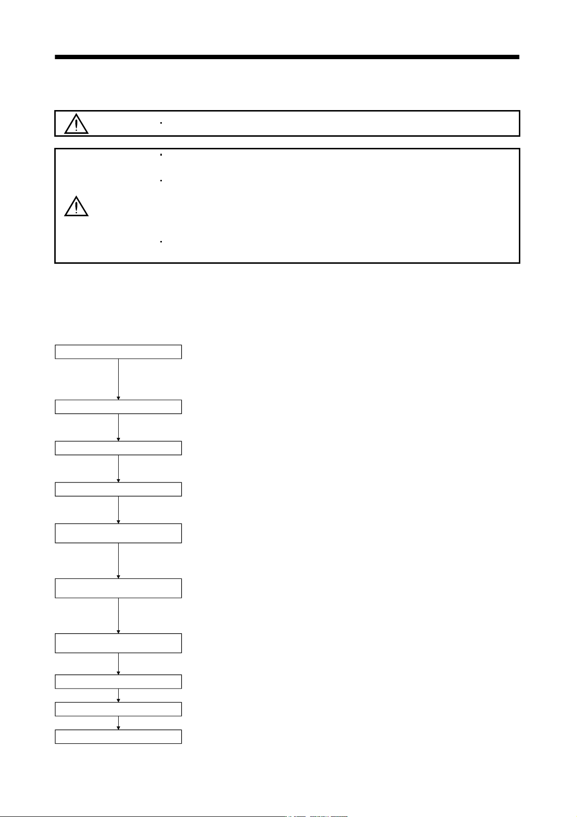
When switching power on for the first time, follow this section to make a startup.
4.1.1 Startup procedure
Wiring check
Surrounding environment check
Axis No. settings
Parameter setting
Test operation of servo motor
alone in test operation mode
Test operation of servo motor
alone by commands
Test operation with servo motor
and machine connected
Gain adjustment
Actual operation
Stop
Check whether the servo amplifier and servo motor are wired correctly using
visual inspection, DO forced output function (section 4.5.1), etc. (Refer to
section 4.1.2.)
Check the surrounding environment of the servo amplifier and servo motor.
(Refer to section 4.1.3.)
Confirm that the axis No. settings for rotary axis setting switch (SW1) and
servo system controller are consistent. (Refer to section 3.12)
Set the parameters as necessary, such as the used control mode and
regenerative option selection. (Refer to chapter 5)
For the test operation, with the servo motor disconnected from the machine
and operated at the speed as low as possible, check whether the servo moto
r
rotates correctly. (Refer to sections 4.5)
For the test operation with the servo motor disconnected from the machine
and operated at the speed as low as possible, give commands to the servo
amplifier and check whether the servo motor rotates correctly.
Connect the servo motor with the machine, give operation commands from the
host command device, and check machine motions.
Make gain adjustment to optimize the machine motions. (Refer to chapter 6.)
Stop giving commands and stop operation.