sh030051g.pdf - 第83页
3 - 28 3. SIGNALS AND WI RING 3.7 Interfaces 3.7.1 Internal connection diagram 3 EM1 CN3 20 DI1 2 DI2 1 2 DI3 1 9 DICOM 5 3 CN3 10 13 9 15 DICOM (Note 2) INP ALM CN3 6 16 7 17 8 18 LA LAR LB LBR LZ LZR RA CN3 MO1 MO2 LG …
3 - 27
3. SIGNALS AND WIRING
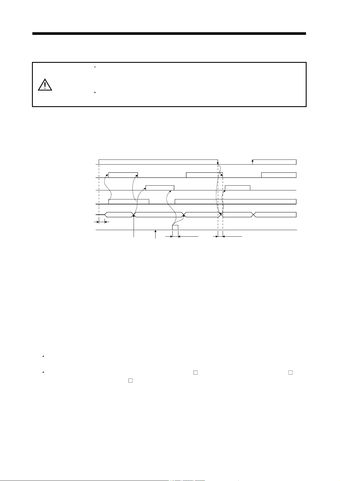
3.6 Alarm occurrence timing chart
CAUTION
When an alarm has occurred, remove its cause, make sure that the operation
signal is not being input, ensure safety, and reset the alarm before restarting
operation.
As soon as an alarm occurs, make the Servo off status and interrupt the main
circuit power.
When an alarm occurs in the servo amplifier, the base circuit is shut off and the servo motor is coated to a stop.
Switch off the main circuit power supply in the external sequence. To deactivate the alarm, power the control
circuit off, then on or give the error reset or CPU reset command from the servo system controller. However,
the alarm cannot be deactivated unless its cause is removed.
ON
OFF
ON
OFF
ON
OFF
NO
YES
ON
OFF
1s
NO
YES
Main circuit
Control circuit
power
Base circuit
Dynamic brake
Servo-on command
(from controller)
Alarm
Reset command
(from controller)
Valid
Invalid
Alarm occurs.
Remove cause of trouble.
50ms or more
60ms or more
NO
Brake operation
Brake operation
Power on
Power off
(Note)
Note. Switch off the main circuit power as soon as an alarm occurs.
(1) Overcurrent, overload 1 or overload 2
If operation is repeated by switching control circuit power off, then on to reset the overcurrent (32), overload
1 (50) or overload 2 (51) alarm after its occurrence, without removing its cause, the servo amplifier and
servo motor may become faulty due to temperature rise. Securely remove the cause of the alarm and also
allow about 30 minutes for cooling before resuming operation.
(2) Regenerative alarm
If operation is repeated by switching control circuit power off, then on to reset the regenerative (30) alarm
after its occurrence, the external regenerative resistor will generate heat, resulting in an accident.
(3) Instantaneous power failure
Undervoltage (10) occurs when the input power is in either of the following statuses.
A power failure of the control circuit power supply continues for 60ms or longer and the control circuit is
not completely off.
The bus voltage dropped to 200VDC or less for the MR-J3- B, to 158VDC or less for the MR-J3- B1, or
to 380VDC or less for the MR-J3-
B4.
3 - 28
3. SIGNALS AND WIRING
3.7 Interfaces
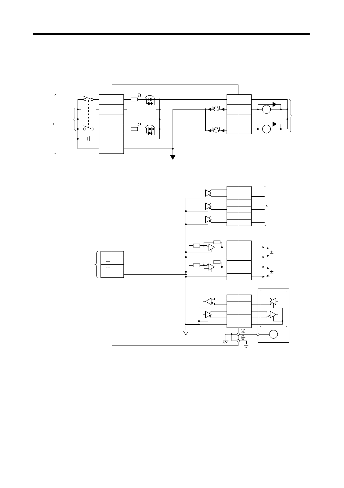
3.7.1 Internal connection diagram
3
EM1
CN3
20
DI1 2
DI2 12
DI3 19
DICOM
5
3
CN3
10
13
9
15
DICOM
(Note 2)
INP
ALM
CN3
6
16
7
17
8
18
LA
LAR
LB
LBR
LZ
LZR
RA
CN3
MO1
MO2
LG
4
14
11
RA
Differential line
driver output
(35mA or less)
<Isolated>
Approx
5.6k
Analog monitor
Servo amplifier
2
4
7
8
MR
MRR
MD
MDR
LG
Encoder
E
Servo motor
(Note 1)
USB
M
D
GND
VBUS
D
1
2
3
5
CN5
LG1
MBR
DOCOM
24VDC
Forced stop
CN2
(Note 3)
(Note 3)
Approx
5.6k
10VDC
10VDC
Note 1. Signal can be assigned for these pins with host controller setting.
For contents of signals, refer to the instruction manual of host controller.
2. This signal cannot be used with speed loop mode.
3. For the sink I/O interface. For the source I/O interface, refer to section 3.7.3.
3 - 29
3. SIGNALS AND WIRING
3.7.2 Detailed description of interfaces
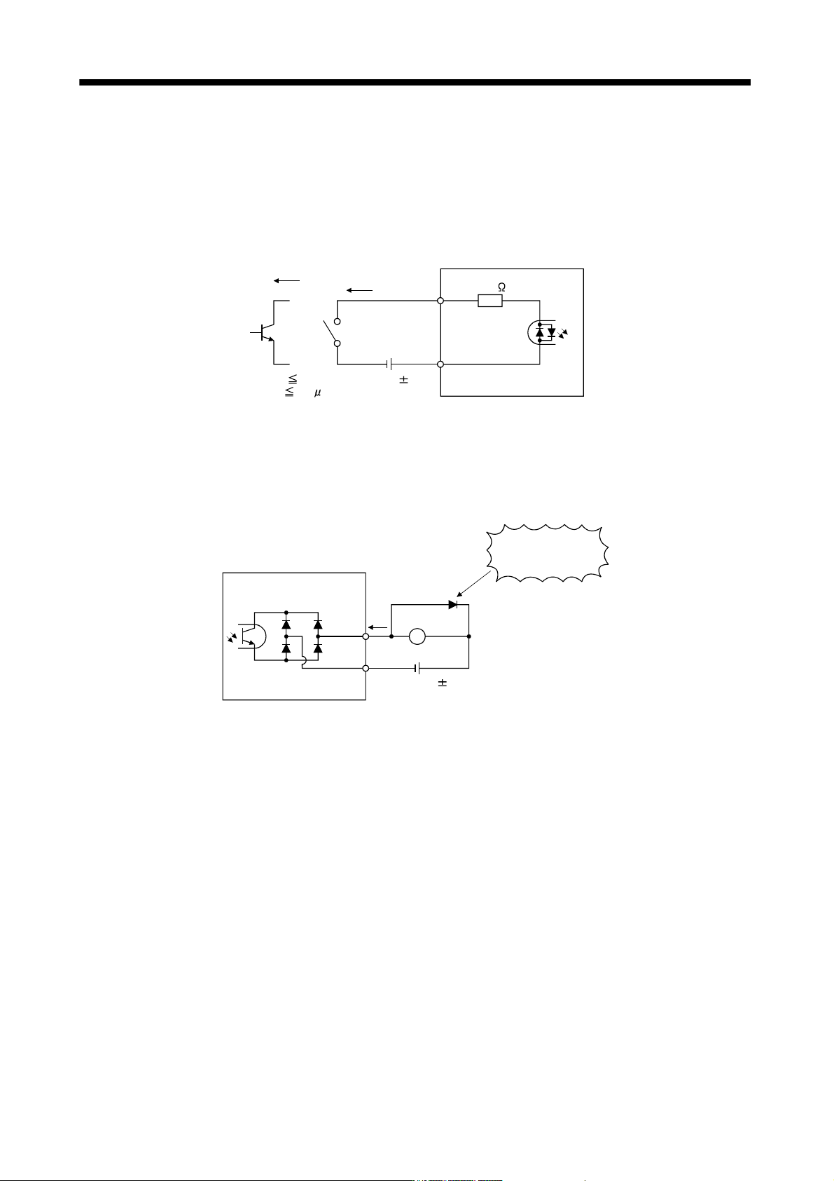
This section provides the details of the I/O signal interfaces (refer to the I/O division in the table) given in
section 3.5. Refer to this section and make connection with the external equipment.
(1) Digital input interface DI-1
Give a signal with a relay or open collector transistor. Refer to section 3.7.3 for the source input.
DICOM
V
CES 1.0V
I
CEO
100
A
TR
24VDC 10%
5.6k
For transistor
Approx. 5mA
Switch
150mA
Servo amplifier
EM1,
etc.
(2) Digital output interface DO-1
A lamp, relay or photocoupler can be driven. Install a diode (D) for an inductive load, or install an inrush
current suppressing resistor (R) for a lamp load. (Rated current: 40mA or less, maximum current: 50mA or
less, inrush current: 100mA or less) A maximum of 2.6V voltage drop occurs in the servo amplifier.
Refer to section 3.7.3 for the source output.
If polarity of diode is
reversed, servo
amplifier will fail.
Servo amplifier
ALM,
etc.
Load
DOCOM
24VDC 10%
150mA
(Note)
Note. If the voltage drop (maximum of 2.6V) interferes with the relay operation, apply high voltage (up to
26.4V) from external source.