sh030051g.pdf - 第125页
5 - 8 5. PARAMETERS 5.1.8 Selection of servo motor rotation direction Parameter Initial value Unit Setting range No. Symbol Name PA14 *POL Rotation direction selection 0 0 1 POINT This parameter is made valid when power …
5 - 7
5. PARAMETERS
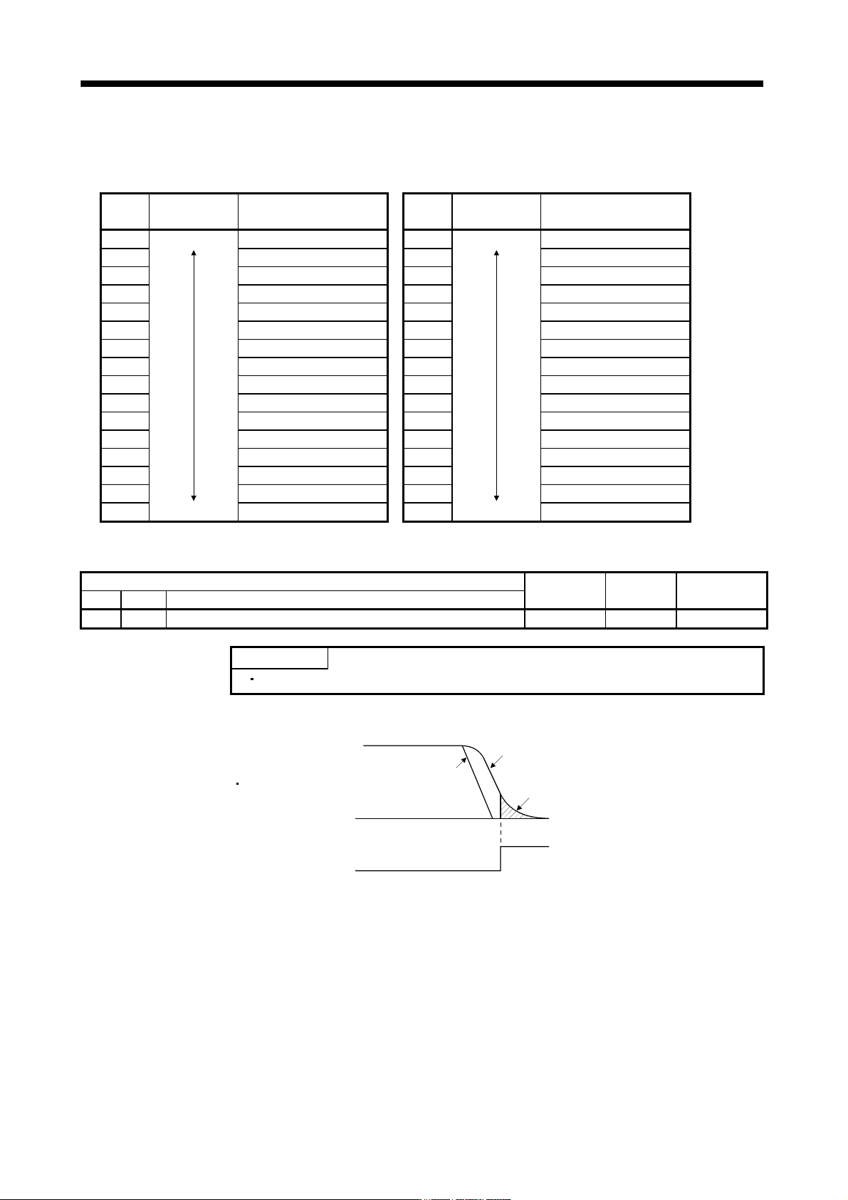
(2) Auto tuning response (parameter No.PA09)
If the machine hunts or generates large gear sound, decrease the set value. To improve performance, e.g.
shorten the settling time, increase the set value.
Setting Response
Guideline for machine
resonance frequency [Hz]
Setting Response
Guideline for machine
resonance frequency [Hz]
1 Low response 10.0 17 Low response 67.1
2
11.3 18
75.6
3 12.7 19 85.2
4 14.3 20 95.9
5 16.1 21 108.0
6 18.1 22 121.7
7 20.4 23 137.1
8 23.0 24 154.4
9 25.9 25 173.9
10 29.2 26 195.9
11 32.9 27 220.6
12 37.0 28 248.5
13 41.7 29 279.9
14 47.0 30 315.3
15 52.9 31 355.1
16 Middle response 59.6 32 Middle response 400.0
5.1.7 In-position range
Parameter
Initial value Unit Setting range
No. Symbol Name
PA10 INP In-position range 100 pulse 0 to 65535
POINT
This parameter cannot be used in the speed control mode.
Set the range, where in position (INP) is output, in the command pulse unit.
Servo motor droop pulse
In-position range [pulse]
Command pulse
Command pulse
Droop pulse
In position (INP)
ON
OFF
5 - 8
5. PARAMETERS
5.1.8 Selection of servo motor rotation direction
Parameter
Initial value Unit Setting range
No. Symbol Name
PA14 *POL Rotation direction selection 0 0 1
POINT
This parameter is made valid when power is switched off, then on after
setting, or when the controller reset has been performed.
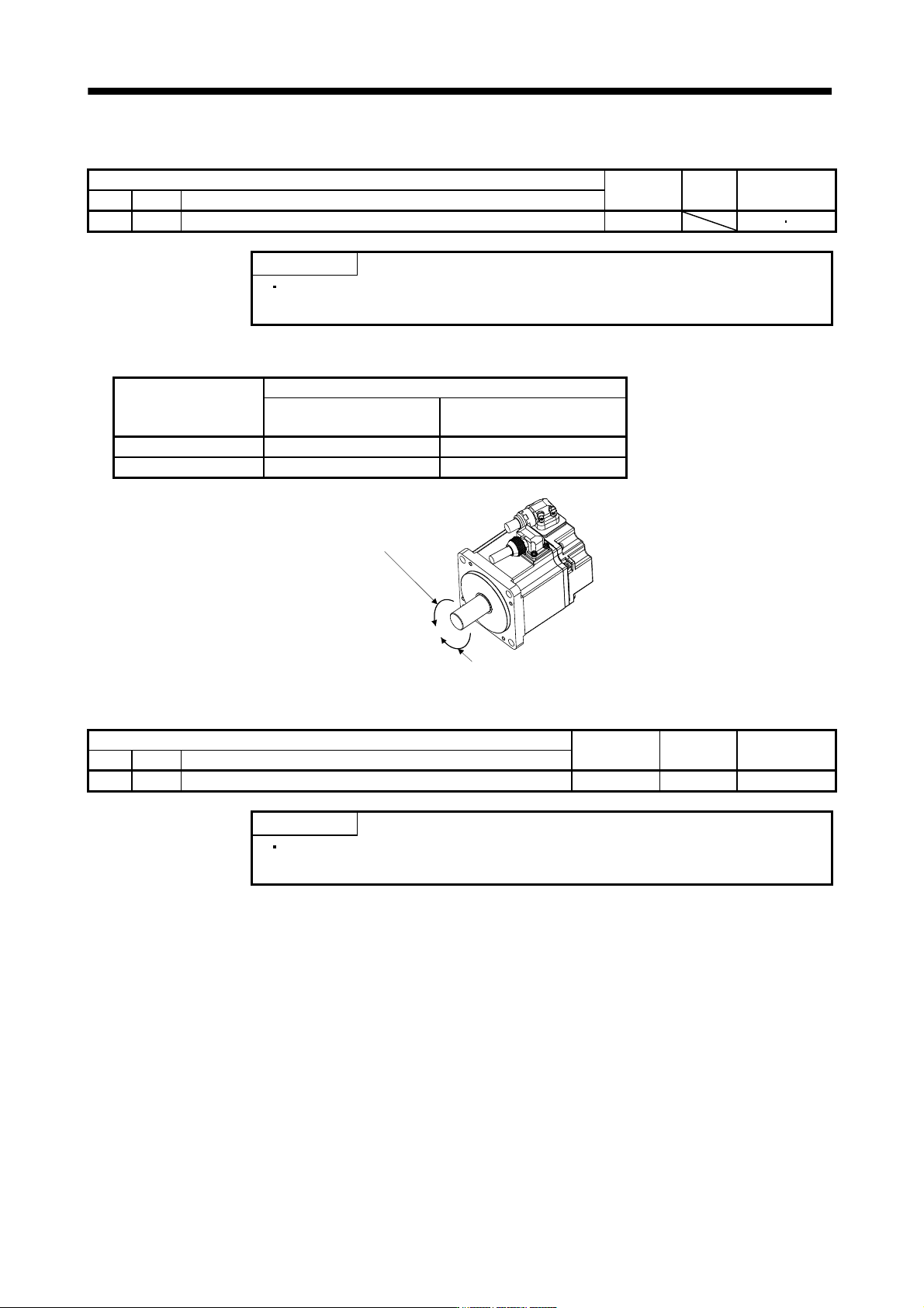
Select servo motor rotation direction relative.
Parameter No.PA14
setting
Servo motor rotation direction
When positioning address
increases
When positioning address
decreases
0 CCW CW
1 CW CCW
Forward rotation (CCW)
Reverse rotation (CW)
5.1.9 Encoder output pulse
Parameter
Initial value Unit Setting range
No. Symbol Name
PA15 *ENR Encoder output pulse 4000 pulse/rev 1 to 65535
POINT
This parameter is made valid when power is switched off, then on after
setting, or when the controller reset has been performed.
Used to set the encoder pulses (A-phase, B-phase) output by the servo amplifier.
Set the value 4 times greater than the A-phase or B-phase pulses.
You can use parameter No.PC03 to choose the output pulse setting or output division ratio setting.
The number of A/B-phase pulses actually output is 1/4 times greater than the preset number of pulses.
The maximum output frequency is 4.6Mpps (after multiplication by 4). Use this parameter within this range.

5 - 9
5. PARAMETERS
(1) For output pulse designation
Set "
0 " (initial value) in parameter No.PC03.
Set the number of pulses per servo motor revolution.
Output pulse
set value [pulses/rev]
For instance, set "5600" to Parameter No.PA15, the actually output A/B-phase pulses are as indicated
below.
4
5600
A B-phase output pulses 1400[pulse]
(2) For output division ratio setting
Set "
1 " in parameter No.PC03.
The number of pulses per servo motor revolution is divided by the set value.
Output pulse
[pulses/rev]
Resolution per servo motor revolution
Set value
For instance, set "8" to Parameter No.PA15, the actually output A/B-phase pulses are as indicated below.
A
B-phase output pulses 8192[pulse]
8
262144
4
1