sh030051g.pdf - 第412页
App. - 9 A PPENDI X App. 6 Selection example of servo motor power cable POINT Selection condition of wire size is as follows. Wire length: 30m or less Depending on the cable selecte d, there may be cases that the cable d…
App. - 8
A
PPENDI
X
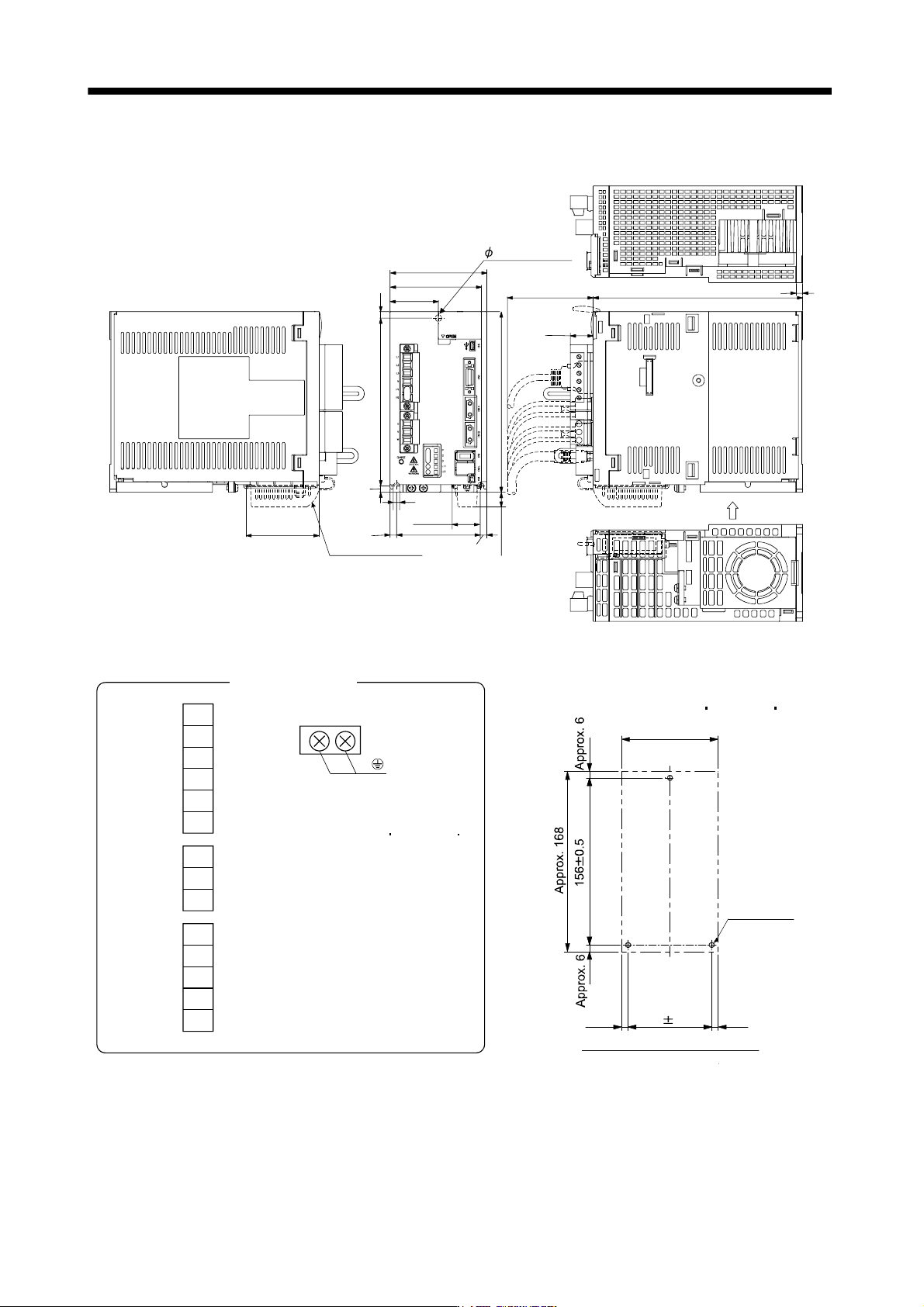
App. 5.4 OUTLINE DRAWINGS (Chapter 9 OUTLINE DRAWINGS)
[Unit: mm]
Approx.14
Approx.
25.5
90
168
6
78
6
45
6
156
6
6 mounting hole
195
21.4
Approx.80
Cooling fan
wind direction
Approx.68
6
85
With MR-J3BAT
6
Mass: 2.3 [kg] (5.07 [lb])
U
V
W
CNP3
P
C
D
L
11
L
21
CNP2
L1
L
2
L
3
N
P
1
P2
CNP1
Terminal signal layout
PE terminal
Screw size: M4
Tightening torque:
1.2 [N m] (10.6 [lb in])
Approx. 90
78 0.3
Approx. 6
Approx. 6
3-M5 screw
Mounting hole process drawing
Mounting screw
Screw size: M5
Tightening torque: 3.24 [N m] (28.7 [lb in])
App. - 9
A
PPENDI
X
App. 6 Selection example of servo motor power cable
POINT
Selection condition of wire size is as follows.
Wire length: 30m or less
Depending on the cable selected, there may be cases that the cable does not
fit into the Mitsubishi optional or recommended cable clamp. Select a cable
clamp according to the cable diameter.
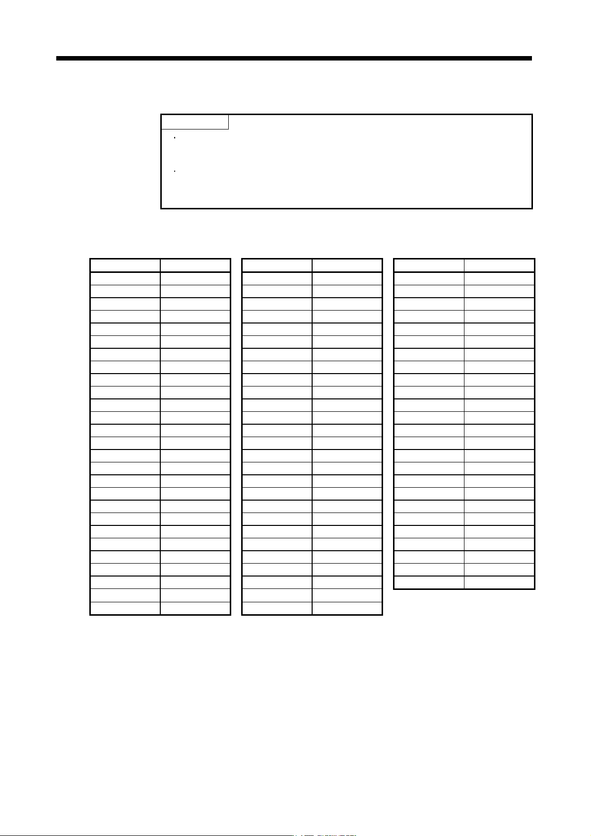
Selection example when using the 600V grade EP rubber insulated chloroprene sheath cab-tire cable (2PNCT)
for servo motor power (U, V, and W) is indicated below.
Servo motor Wire size [mm
2
] Servo motor Wire size [mm
2
] Servo motor Wire size [mm
2
]
HF-SP52 1.25 HC-LP152 2 HA-LP30K2 60
HF-SP102 1.25 HC-LP202 3.5 HA-LP37K2 60
HF-SP152 2 HC-LP302 5.5 HA-LP6014 5.5
HF-SP202 2 HC-UP72 1.25 HA-LP8014 5.5
HF-SP352 3.5 HC-UP152 2 HA-LP12K14 8
HF-SP502 5.5 HC-UP202 3.5 HA-LP15K14 14
HF-SP702 8 HC-UP352 5.5 HA-LP20K14 14
HF-SP51 1.25 HC-UP502 5.5 HA-LP25K14 22
HF-SP81 1.25 HA-LP601 8 HA-LP30K14 22
HF-SP121 2 HA-LP801 14 HA-LP37K14 22
HF-SP201 2 HA-LP12K1 14 HA-LP701M4 5.5
HF-SP301 3.5 HA-LP15K1 22 HA-LP11K1M4 8
HF-SP421 5.5 HA-LP20K1 38 HA-LP15K1M4 14
HF-SP524 1.25 HA-LP25K1 38 HA-LP22K1M4 14
HF-SP1024 1.25 HA-LP30K1 38 HA-LP30K1M4 22
HF-SP1524 2 HA-LP37K1 60 HA-LP37K1M4 22
HF-SP2024 2 HA-LP701M 8 HA-LP45K1M4 38
HF-SP3524 2 HA-LP11K1M 14 HA-LP50K1M4 38
HF-SP5024 3.5 HA-LP15K1M 22 HA-LP11K24 8
HF-SP7024 5.5 HA-LP22K1M 38 HA-LP15K24 14
HC-RP103 2 HA-LP30K1M 60 HA-LP22K24 14
HC-RP153 2 HA-LP37K1M 60 HA-LP30K24 22
HC-RP203 (Note) 3.5 HA-LP502 5.5 HA-LP37K24 22
HC-RP353 (Note) 5.5 HA-LP702 8 HA-LP45K24 38
HC-RP503 (Note) 5.5 HA-LP11K2 14 HA-LP55K24 38
HC-LP52 1.25 HA-LP15K2 22
HC-LP102 1.25 HA-LP22K2 22
Note. Use a composite cable and others when combining with wiring of the electromagnetic brake power in the same cable.
REVISIONS
*The manual number is given on the bottom left of the back cover.
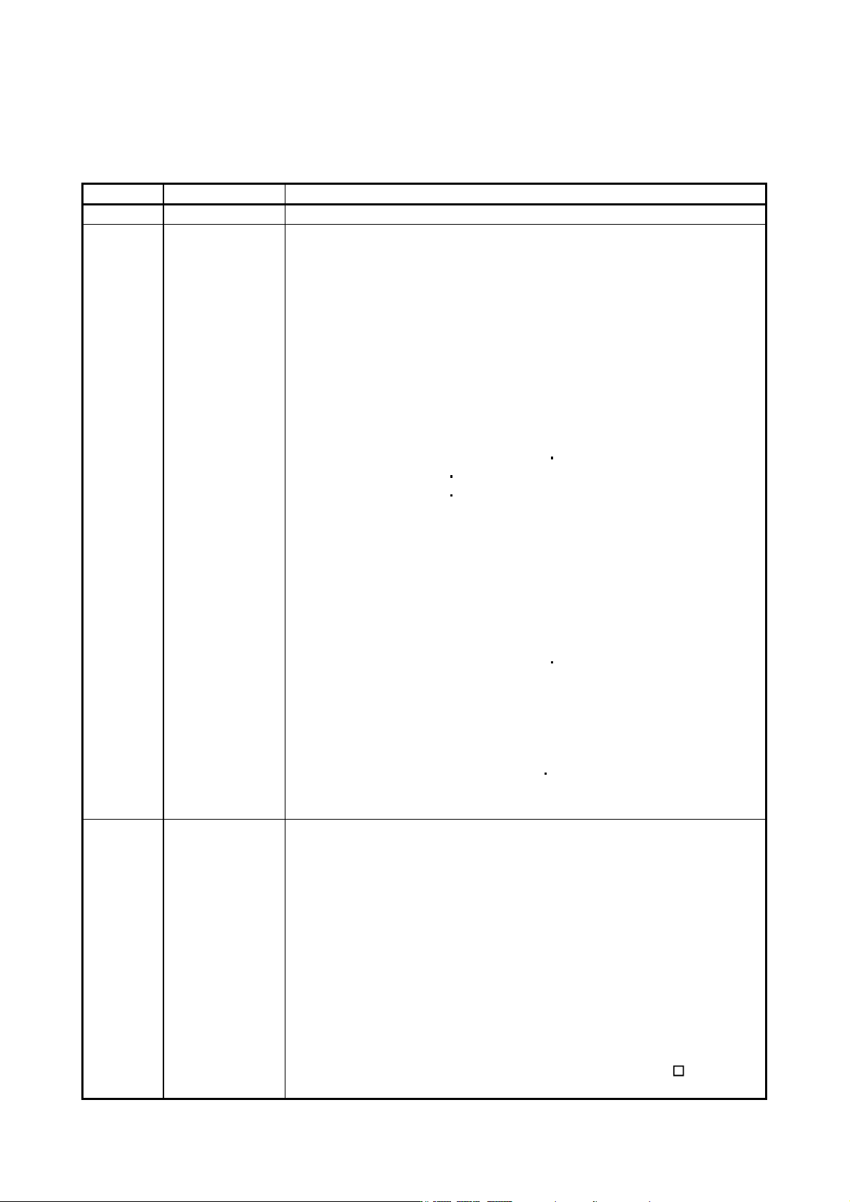
Print Data *Manual Number Revision
May. 2005 SH(NA)030051-A First edition
Jan. 2006 SH(NA)030051-B Addition of servo amplifier MR-J3-11KB(4), 15KB(4) and 22KB(4)
Addition of servo motor HC-RP, HC-UP, HC-LP and HA-LP4 series
Section 1.5 (2)
: Addition of regeneration brake resistor-less specification
Section 1.7.2 : Addition of removal and reinstallation of front cover for
11KB(4) or more
Section 2.1
: (1) Addition of 7kW or less
(2) Addition of 11kW or more
Section 3.7.1
: Error correction of differential line driver output as 35mA
Section 3.8 (2)
: Addition of "For CN2 connector"
Section 3.11.2 (4)
: Addition of time from invalid to valid of electromagnetic brake
interlock
Section 5.1.3
: Addition of sentence when using with 11KB or more for
parameter No.PA02 00
Addition of FA
Section 5.3.1
: PC13 PC14 description change
Section 5.3.2
: PC13 PC14 description change
Section 5.3.3 (2) : Addition of Note3
Section 5.3.3 (3)
: Partial figure change of analog monitor block
Section 5.4.2
: Partial sentence addition of parameter No.PD07
Section 8.2 : Addition of "IGBT" to Cause 2. of alarm No. 32 indicated as
Display in the remedies list for alarms
Section 8.3
: Addition of POINT
Section 11.1.1 : Partial figure addition
Section 11.2 (3)
: Addition of sentence when using with 11KB or more for
parameter No.PA02 00
Addition of FA
Section 11.2 (5) (d) : Addition
Section 11.5
: Addition
Section 11.6
: Addition
Section 11.7
: Error correction
Section 11.10
: Addition
Section 11.11
: Addition of cooling fan thermal
Addition of Table 11.2, Note. 2
Section 11.19 : Addition of EMC filter HF3100A-UN
Jul. 2007 SH(NA)030051-C Addition of servo amplifier MR-J3-60B4 to 350B4
Addition of servo amplifier MR-J3-500B4 and 700B4
Addition of servo motor HF-SP524 / 1024 / 1524 / 2024 / 3524
Addition of drive units MR-J3-DU30KB(4), 37KB(4), 45KB4 and 55KB4
Addition of converter unit MR-J3-CR55K(4)
Deletion of setup software notation
Compliance with RoHS
Safety instructions 1.: To prevent electric shock: Addition of Note for 30kW or more
Safety instructions 4.: Additional instructions (2): Correction of the connection
diagram
Conformance with UL/C-UL standard (4): Addition of the capacitor discharge time
for 30kW or more
Conformance with UL/C-UL standard (5): Addition of the fuse for 30kW or more
About the manuals
Section 1.2
: Addition of description about MR-J3-DU B(4)
: Power supply description change