sh030051g.pdf - 第375页
13 - 74 13. SERVO AMPLIFIERS WI TH A LARGE CAPACITY ( 30k TO 55kW ) (2) MR-J3CDL05M(0.5m) Protection coordination cable CAUTION Connect protection coo rdination cables correctly if they are fabricated. Otherwise, the sys…
13 - 73
13. SERVO AMPLIFIERS WITH A LARGE CAPACITY
(
30k TO 55kW
)
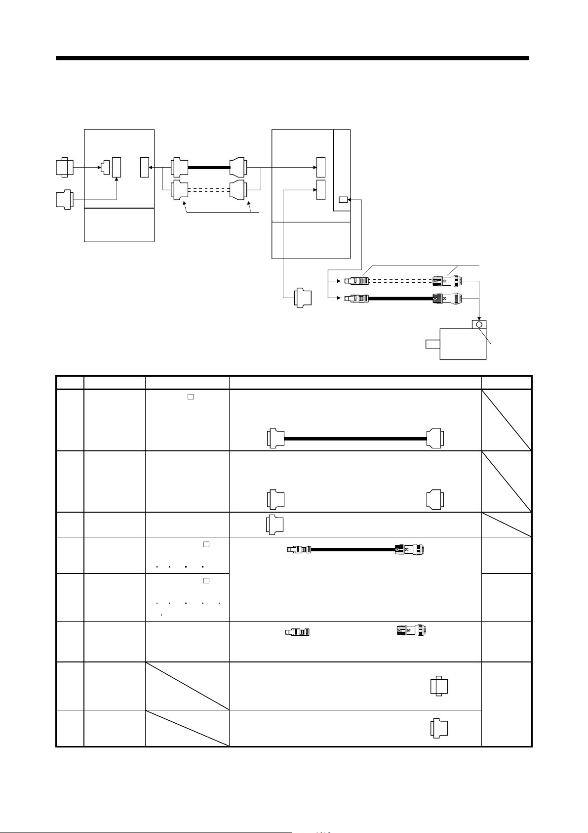
(1) Makeup of cables and like
The following shows the cable makeup for connection with the servo motor and other model.
3)
Drive unitConverter unit
4) 5)
6)
Terminal
box
Servo motor
HA-LP
CNP1 CN40
CN1
7)
8)
2)
1)
CN40A
CN40B
CN2
No. Product Model Description Application
1) Protection
coordination
cable
MR-J3CDL
M
Refer to (2) of this
section.
Connector: 10120-3000PE
Shell kit: 10320-52F0-008
(3M or equivalent)
Connector: PCR-S20FS+
Case: PCR-LS20LA1
(Honda Tsushin Kogyo)
2) Connector set MR-J2CN1-A
Refer to (2) of this
section.
Connector: 10120-3000PE
Shell kit: 10320-52F0-008
(3M or equivalent)
Connector: PCR-S20FS+
Shell kit: PCR-LS20LA1
(Honda Tsushin Kogyo)
3) Termination
connector
MR-J3-TM
4) Encoder cable MR-J3ENSCBL M-L
Cable length:
2
5 10 20 30m
IP67
Standard
life
5) Encoder cable MR-J3ENSCBL M-H
Cable length:
2
5 10 20 30
40 50m
For HA-LP series
Refer to section 11.1.2 (4) for details.
IP67
Long flex
life
6) Encoder
connector set
MR-J3SCNS
For HA-LP series
Refer to section 11.1.2 (4) for details.
IP67
7) Magnetic
contactor
wiring
connector
Converter unit side connector
(Phoenix Contact)
Socket: GFKC 2.5/2-STF-7.62
Supplied
with
converter
unit
8) Digital
I/O connector
Converter unit side connector
(DDK)
Connector: 17JE23090-02(D8A)K11-CG
13 - 74
13. SERVO AMPLIFIERS WITH A LARGE CAPACITY
(
30k TO 55kW
)
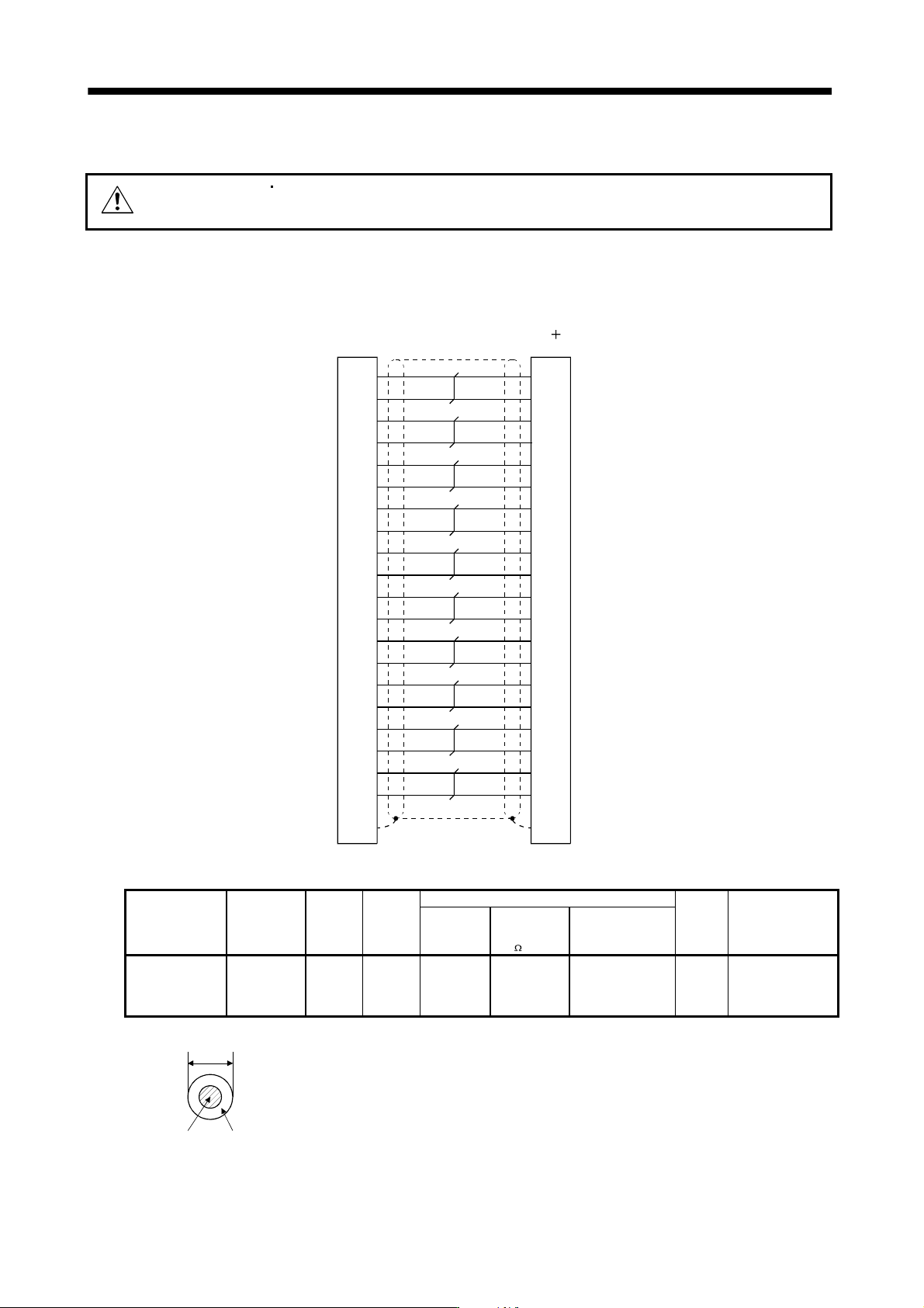
(2) MR-J3CDL05M(0.5m) Protection coordination cable
CAUTION
Connect protection coordination cables correctly if they are fabricated.
Otherwise, the system may perform unexpected operation.
When fabricating a protection coordination cable, use the recommended wires given in section 13.9.4, and
fabricate a protection coordination cable as shown in the wiring diagram in this section.
MR-J3CDL05M
1
11
2
12
3
13
4
14
5
15
6
16
7
17
8
18
9
19
10
20
Plate
1
11
2
12
3
13
4
14
5
15
6
16
Plate
7
17
8
18
9
19
10
20
ACD2
ACD2*
ACD3
ACD3*
PAL
PAL*
ACD1
ACD1*
LG
LG
GOF
GOF*
PMC
PMC*
PSD
PSD*
LG
LG
PRD
PRD*
SD
10120-3000PE (Connector)
10320-52F0-008 (Shell kit)
PCR-S20FS (Connector)
PCR-LS20LA1 (Case)
Drive unit sideConverter unit side
Table 13.2 Recommended wire
Model
Length
[m(ft)]
Core size
[mm
2
]
Number
of cores
Characteristics of one core
(Note 2)
Finishing
OD
[mm]
Wire model
Structure
[Wires/mm]
Conductor
resistance
[
/mm]
Insulation coating
OD d[mm]
(Note 1)
MR-J3CDL05M
0.5 to 5
(1.64 to 16.4)
0.08
20
(10 pairs)
7/0.127 222 0.38 6.1
UL20276 AWG#28
10pair (CREAM)
Note 1. d is as shown below.
d
Conductor
Insulation sheath
2. Standard OD. Max. OD is about 10% greater.
13 - 75
13. SERVO AMPLIFIERS WITH A LARGE CAPACITY
(
30k TO 55kW
)
13.9.2 Regenerative option
CAUTION
The specified combinations of regenerative options, converter unit and drive unit
may only be used. Otherwise, a fire may occur.
POINT
The calculation method of regenerative energy is the same as that for servo
amplifiers with 22kW or less. Refer to section 11.2 (2).
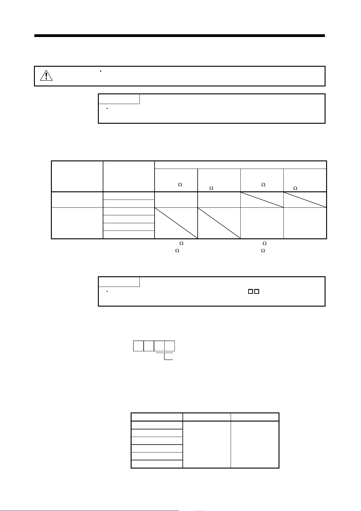
(1) Combination and regenerative power
The regenerative power values in the table are the regenerative power of the resistor and are not the rated
power.
Converter unit Drive unit
Regenerative Power [W]
MR-RB139
(1.3
)
(Note 1) Three
MR-RB137
(1.3
) in parallel
MR-RB136-4
(5
)
(Note 2) Three
MR-RB138-4
(5
) in parallel
MR-J3-CR55K
MR-J3-DU30KB
1300 3900
MR-J3-DU37KB
MR-J3-DU30KB4
1300 3900 MR-J3-CR55K4
MR-J3-DU37KB4
MR-J3-DU45KB4
MR-J3-DU55KB4
Note. 1. The composite resistor value of three options is 1.3 . The resistor value of one option is 4 .
2. The composite resistor value of three options is 5
. The resistor value of one option is 15 .
(2) Parameter setting
POINT
Always set parameter No.PA02 of the drive unit to “ 00”(Not used) since
the regenerative option cannot be connected to the drive unit.
When using the regenerative option, set the parameter of the converter unit. Match parameter No.PA01 to
the regenerative option used.
Regenerative option selection
00: Not used
01: MR-RB139
02: MR-RB137 (3 pcs.)
11: MR-RB136-4
12: MR-RB138-4 (3 pcs.)
Parameter No.PA01
00
(3) Regenerative loss of drive unit and servo motor
Drive unit Inverse efficiency [%] C charge [J]
MR-J3-DU30KB
MR-J3-DU37KB
MR-J3-DU30KB4
90 450
MR-J3-DU37KB4
MR-J3-DU45KB4
MR-J3-DU55KB4