sh030051g.pdf - 第96页
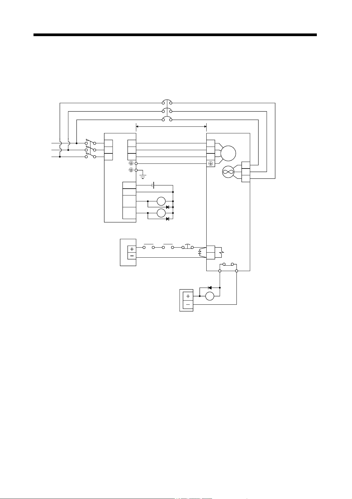
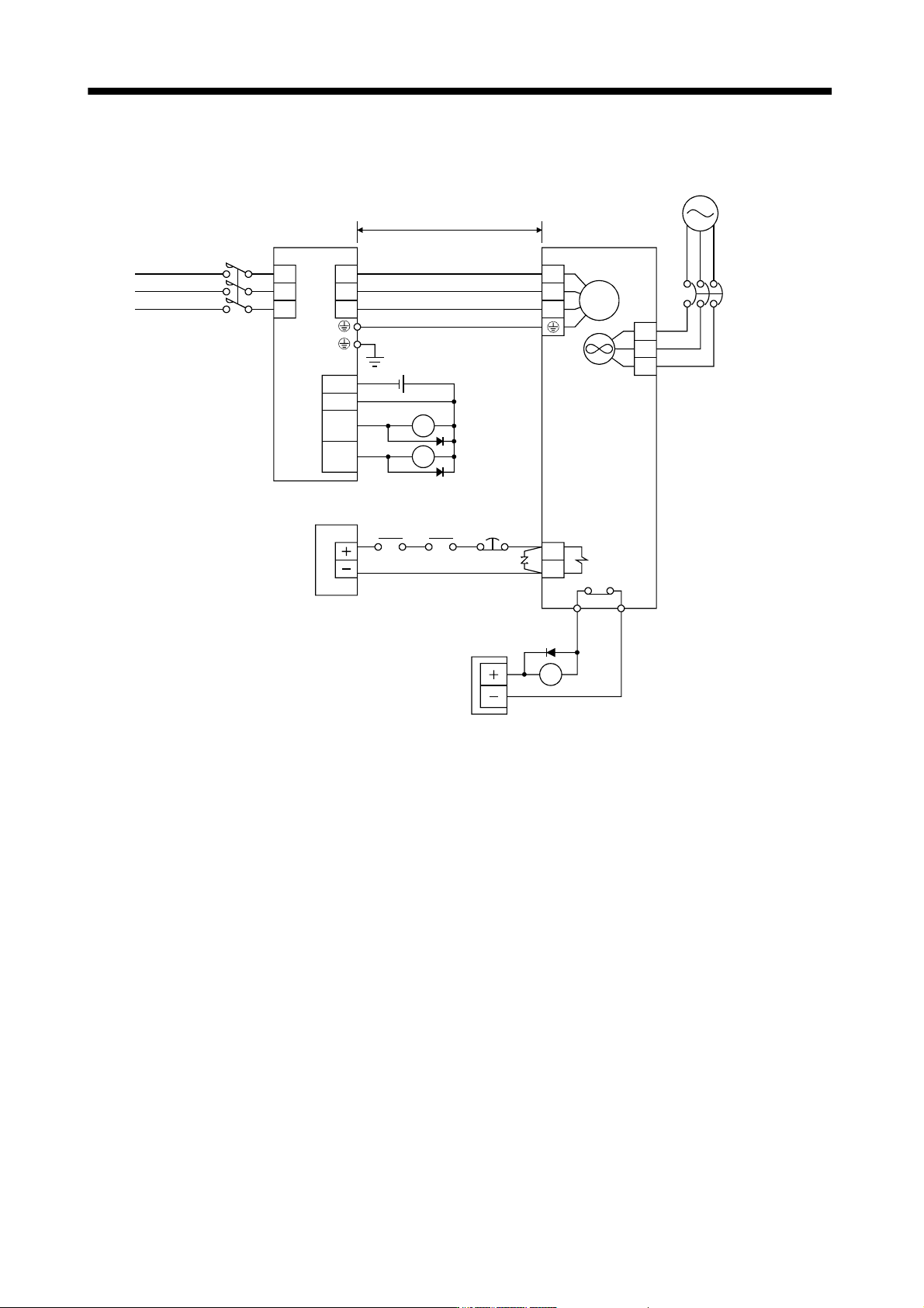
3 - 41 3. SIGNALS AND WI RING 2) 400V class Servo mot or (Note 1) Servo am plifier U V W B1 B2 U V W 24VDC power supply for electromagnetic brake 50m or less Forced stop (EM1) Trouble (ALM) RA1 24VDC ALM DOCOM DICOM MBR …
3 - 40
3. SIGNALS AND WIRING
(3) HA-LP series servo motor
(a) Wiring diagrams
Refer to section 11.11 for the cables used for wiring.
1) 200V class
Servo motor
(Note 1)
Servo amplifier
U
V
W
B1
B2
U
V
W
24VDC power
supply for
electromagnetic
brake
50m or less
Forced
stop
(EM1)
Trouble
(ALM)
RA1
24VDC
ALM
DOCOM
DICOM
MBR
CN3
RA1
RA2
Electromagnetic
brake interlock
(MBR)
RA2
RA3
M
Cooling fan
(Note 2)
24VDC
power supply
OHS2OHS1 Servo motor
thermal relay
(Note 3)
L1
L2
L3
BU
BV
BW
TE
MC
NFB
Note 1. There is no polarity in electromagnetic brake terminals B1 and B2.
2. Cooling fan power supply of the HA-LP601, the HA-LP701M and the HA-LP11K2 servo motor is 1-phase. Power supply
specification of the cooling fan is different from that of the servo amplifier. Therefore, separate power supply is required.
3. Configure the power supply circuit which turns off the magnetic contactor after detection of servo motor thermal.
3 - 41
3. SIGNALS AND WIRING
2) 400V class
Servo motor
(Note 1)
Servo amplifier
U
V
W
B1
B2
U
V
W
24VDC power
supply for
electromagnetic
brake
50m or less
Forced
stop
(EM1)
Trouble
(ALM)
RA1
24VDC
ALM
DOCOM
DICOM
MBR
CN3
RA1
RA2
Electromagnetic
brake interlock
(MBR)
RA2
RA3
M
Cooling fan
(Note 2)
24VDC
power supply
OHS2OHS1 Servo motor
thermal relay
(Note 3)
L
1
L
2
L
3
BU
BV
BW
TE
MC
(Note4)
Cooling fan power supply
NFB
Note 1. There is no polarity in electromagnetic brake terminals B1 and B2.
2. There is no BW when the power supply of the cooling fan is a 1-phase.
3. Configure the power supply circuit which turns off the magnetic contactor after detection of servo motor thermal.
4. For the cooling fan power supply, refer to (3) (b) of this section.
3 - 42
3. SIGNALS AND WIRING
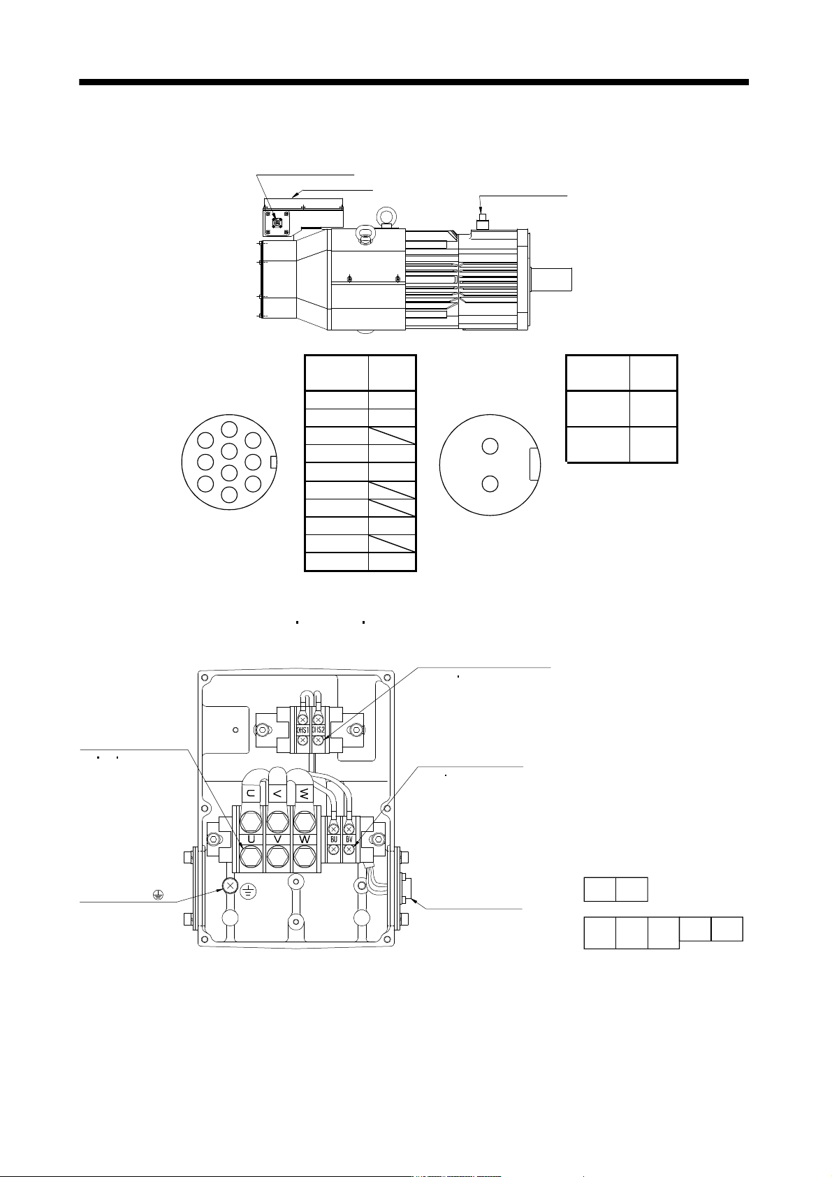
(b) Servo motor terminals
Terminal box
Encoder connector
CM10-R10P
Brake connector
MS3102A10SL-4P
Encoder connector signal
allotment
CM10-R10P
5
6
1
4
3
2
8
7
9
10
Terminal
No.
Signal
Brake connector signal
allotment
MS3102A10SL-4P
1
2
Terminal
No.
Signal
1 MR
1
B1
2 MRR (Note)
3
2
B2
4 BAT (Note)
5 LG Note. For the motor
with an
electromagnetic
brake, supply
electromagnetic
brake power
(24VDC). There
is no polarity.
6
7
8 P5
9
10 SHD
Terminal box inside (HA-LP601(4)
701M(4) 11K2(4) )
Thermal sensor terminal
block
(OHS1 OHS2) M4 screw
Cooling fan terminal
block
(BU BV) M4 screw
Encoder connector
CM10-R10P
Motor power supply
terminal block
(U V W) M6 screw
Earth terminal( )
M6 screw
Terminal block signal
arrangement
UVW
BU BV
OHS1OHS2