sh030051g.pdf - 第5页
A - 4 CAUTION Provide adequate protection to prevent screws and ot her conductive matter, oil and other combustible matter from entering the converter uni t, servo amplifier (drive unit), and servo motor. Do not drop or …
A - 3
4. Additional instructions
The following instructions should also be fully noted. Incorrect handling may cause a fault, injury, electric shock,
etc.
(1) Transportation and installation
CAUTION
Transport the products correctly according to their weights.
Stacking in excess of the specified number of products is not allowed.
Do not carry the servo motor by the cables, shaft or encoder.
Do not hold the front cover to transport the converter unit and servo amplifier (drive unit). The converter
unit and servo amplifier (drive unit) may drop.
Install the converter unit and servo amplifier (drive unit) in a load-bearing place in accordance with the
Instruction Manual.
Do not climb or stand on servo equipment. Do not put heavy objects on equipment.
The converter unit, servo amplifier (drive unit), and servo motor must be installed in the specified
direction.
Leave specified clearances between the converter unit, servo amplifier (drive unit), and control enclosure
walls or other equipment.
Do not install or operate the converter unit, servo amplifier (drive unit), and servo motor which has been
damaged or has any parts missing.
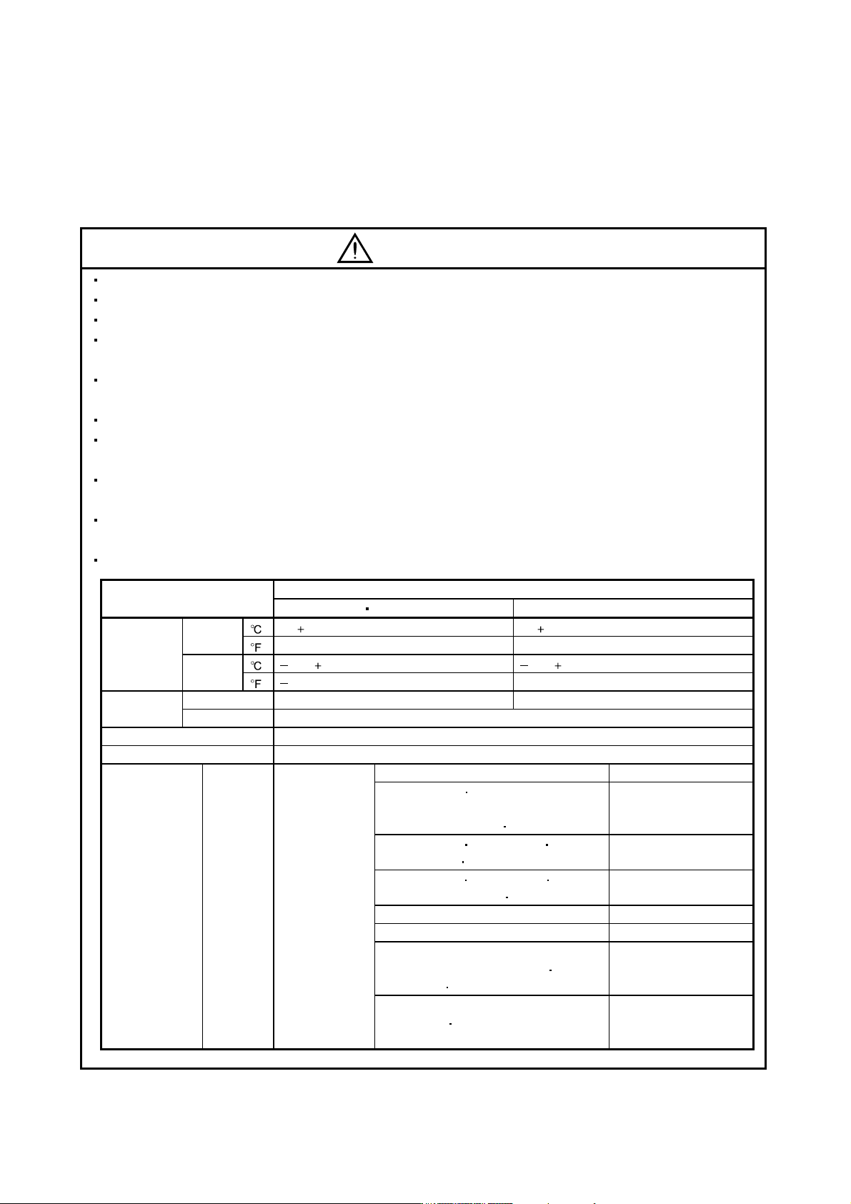
When you keep or use it, please fulfill the following environmental conditions.
Environment
Conditions
Converter unit servo amplifier (drive unit) Servo motor
Ambient
temperature
In
operation
[
] 0 to 55 (non-freezing) 0 to 40 (non-freezing)
[] 32 to 131 (non-freezing) 32 to 104 (non-freezing)
In storage
[ ] 20 to 65 (non-freezing) 15 to 70 (non-freezing)
[] 4 to 149 (non-freezing) 5 to 158 (non-freezing)
Ambient
humidity
In operation 90%RH or less (non-condensing) 80%RH or less (non-condensing)
In storage 90%RH or less (non-condensing)
Ambience Indoors (no direct sunlight) Free from corrosive gas, flammable gas, oil mist, dust and dirt
Altitude Max. 1000m (3280 ft) above sea level
(Note)
Vibration
[m/s
2
] 5.9 or less
HF-MP series HF-KP series X, Y: 49 m/s
2
HF-SP51 81 HF-SP52 to 152
HF-SP524 to 1524 HC-RP Series
HC-UP72
152
X, Y: 24.5 m/s
2
HF-SP121 201 HF-SP202 352
HF-SP2024
3524 HC-UP202 to 502
X: 24.5 m/s
2
Y: 49 m/s
2
HF-SP301 421 HF-SP502 702
HF-SP5024
7024
X: 24.5 m/s
2
Y: 29.4 m/s
2
HC-LP52 to 152 X: 9.8 m/s
2
Y: 24.5 m/s
2
HC-LP202 to 302 X: 19.6 m/s
2
Y: 49 m/s
2
HA-LP601 to 12K1 HA-LP701M to 15K1M
HA-LP502 to 22K2 HA-LP6014
12K14
HA-LP701M4
15K1M4 HA-LP11K24 to 22K24
X: 11.7 m/s
2
Y: 29.4 m/s
2
HA-LP15K1 to 37K1 HA-LP22K1M to 37K1M
HA-LP30K2
37K2 HA-LP15K14 to 37K14
HA-LP22K1M4 to 50K1M4 HA-LP30K24 to 55K24
X, Y: 9.8 m/s
2
Note. Except the servo motor with reduction gear.
A - 4
CAUTION
Provide adequate protection to prevent screws and other conductive matter, oil and other combustible
matter from entering the converter unit, servo amplifier (drive unit), and servo motor.
Do not drop or strike converter unit, servo amplifier (drive unit), or servo motor. Isolate from all impact
loads.
Securely attach the servo motor to the machine. If attach insecurely, the servo motor may come off during
operation.
The servo motor with reduction gear must be installed in the specified direction to prevent oil leakage.
Take safety measures, e.g. provide covers, to prevent accidental access to the rotating parts of the servo
motor during operation.
Never hit the servo motor or shaft, especially when coupling the servo motor to the machine. The encoder
may become faulty.
Do not subject the servo motor shaft to more than the permissible load. Otherwise, the shaft may break.
When the equipment has been stored for an extended period of time, consult Mitsubishi.
(2) Wiring
CAUTION
Wire the equipment correctly and securely. Otherwise, the servo motor may operate unexpectedly.
Do not install a power capacitor, surge absorber or radio noise filter (FR-BIF (-H) option) between the
servo motor and servo amplifier (drive unit).
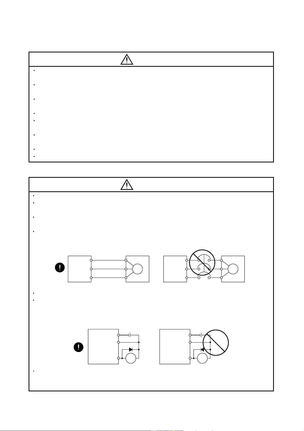
Connect the wires to the correct phase terminals (U, V, W) of the servo amplifier (drive unit) and servo
motor. Otherwise, the servo motor does not operate properly.
Connect the servo motor power terminal (U, V, W) to the servo motor power input terminal (U, V, W)
directly. Do not let a magnetic contactor, etc. intervene.
U
Servo motor
M
V
W
U
V
W
U
M
V
W
U
V
W
Servo amplifier
(drive unit)
Servo motor
Servo amplifier
(drive unit)
Do not connect AC power directly to the servo motor. Otherwise, a fault may occur.
The surge absorbing diode installed on the DC output signal relay of the servo amplifier (drive unit) must
be wired in the specified direction. Otherwise, the forced stop (EM1) and other protective circuits may not
operate.
Control
output
signal
Control
output
signal
RA
DOCOM
DICOM
24VDC
RA
DOCOM
DICOM
24VDC
Servo amplifier
(drive unit)
Servo amplifier
(drive unit)
When the cable is not tightened enough to the terminal block (connector), the cable or terminal block
(connector) may generate heat because of the poor contact. Be sure to tighten the cable with specified
torque.
A - 5
(3) Test run adjustment
CAUTION
Before operation, check the parameter settings. Improper settings may cause some machines to perform
unexpected operation.
The parameter settings must not be changed excessively. Operation will be insatiable.
(4) Usage
CAUTION
Provide an external emergency stop circuit to ensure that operation can be stopped and power switched
off immediately.
Any person who is involved in disassembly and repair should be fully competent to do the work.
Before resetting an alarm, make sure that the run signal of the servo amplifier (drive unit) is off to prevent
an accident. A sudden restart is made if an alarm is reset with the run signal on.
Do not modify the equipment.
Use a noise filter, etc. to minimize the influence of electromagnetic interference, which may be caused by
electronic equipment used near the converter unit and servo amplifier (drive unit).
Burning or breaking a converter unit and servo amplifier (drive unit) may cause a toxic gas. Do not burn or
break a converter unit and servo amplifier (drive unit).
Use the converter unit and servo amplifier (drive unit) with the specified servo motor.
The electromagnetic brake on the servo motor is designed to hold the motor shaft and should not be used
for ordinary braking.
For such reasons as service life and mechanical structure (e.g. where a ball screw and the servo motor
are coupled via a timing belt), the electromagnetic brake may not hold the motor shaft. To ensure safety,
install a stopper on the machine side.