sh030051g.pdf - 第56页
3 - 1 3. SIGNALS AND WIRING 3. SIGNALS AND WIRING WARNING Any person who is involved in wiring shou ld be fu lly competent to do the work. Before wiring, turn off the power and wait for 15 minutes or more un til the char…
2 - 6
2. INSTALLATION
2.5 Inspection items
WARNING
Before starting maintenance and/or inspection, turn off the power and wait for 15
minutes or more until the charge lamp turns off. Then, confirm that the voltage
between P(
) and N( ) is safe with a voltage tester and others. Otherwise, an
electric shock may occur. In addition, always confirm from the front of the servo
amplifier whether the charge lamp is off or not.
Any person who is involved in inspection should be fully competent to do the work.
Otherwise, you may get an electric shock. For repair and parts replacement,
contact your safes representative.
POINT
Do not test the servo amplifier with a megger (measure insulation resistance),
or it may become faulty.
Do not disassemble and/or repair the equipment on customer side.
It is recommended to make the following checks periodically.
(1) Check for loose terminal block screws. Retighten any loose screws.
(2) Check the cables and the like for scratches and cracks. Perform periodic inspection according to operating
conditions.
2.6 Parts having service lives
The following parts must be changed periodically as listed below. If any part is found faulty, it must be changed
immediately even when it has not yet reached the end of its life, which depends on the operating method and
environmental conditions. For parts replacement, please contact your sales representative.
Part name Life guideline
Servo amplifier
Smoothing capacitor 10 years
Relay
Number of power-on and number of emergency
stop times : 100,000 times
Cooling fan 10,000 to 30,000hours (2 to 3 years)
Absolute position battery Refer to section 12.2
(1) Smoothing capacitor
Affected by ripple currents, etc. and deteriorates in characteristic. The life of the capacitor greatly depends
on ambient temperature and operating conditions. The capacitor will reach the end of its life in 10 years of
continuous operation in normal air-conditioned environment.
(2) Relays
Their contacts will wear due to switching currents and contact faults occur. Relays reach the end of their life
when the cumulative number of power-on and emergency stop times is 100,000, which depends on the
power supply capacity.
(3) Servo amplifier cooling fan
The cooling fan bearings reach the end of their life in 10,000 to 30,000 hours. Normally, therefore, the
cooling fan must be changed in a few years of continuous operation as a guideline.
It must also be changed if unusual noise or vibration is found during inspection.
3 - 1
3. SIGNALS AND WIRING
3. SIGNALS AND WIRING
WARNING
Any person who is involved in wiring should be fully competent to do the work.
Before wiring, turn off the power and wait for 15 minutes or more until the charge
lamp turns off. Then, confirm that the voltage between P(
) and N( ) is safe with
a voltage tester and others. Otherwise, an electric shock may occur. In addition,
always confirm from the front of the servo amplifier whether the charge lamp is off
or not.
Ground the servo amplifier and the servo motor securely.
Do not attempt to wire the servo amplifier and servo motor until they have been
installed. Otherwise, you may get an electric shock.
The cables should not be damaged, stressed excessively, loaded heavily, or
pinched. Otherwise, you may get an electric shock.
CAUTION
Wire the equipment correctly and securely. Otherwise, the servo motor may
operate unexpectedly, resulting in injury.
Connect cables to correct terminals to prevent a burst, fault, etc.
Ensure that polarity ( , ) is correct. Otherwise, a burst, damage, etc. may occur.
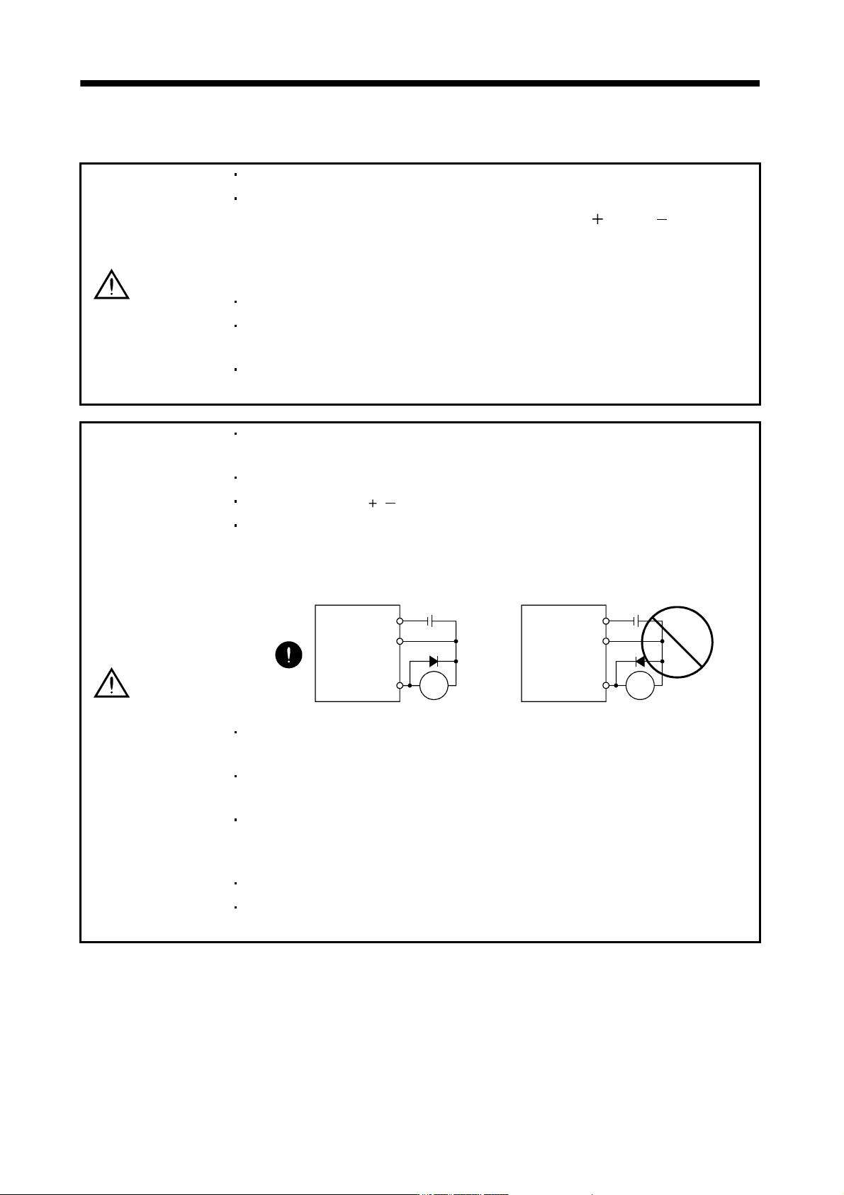
The surge absorbing diode installed to the DC relay designed for control output
should be fitted in the specified direction. Otherwise, the signal is not output due to
a fault, disabling the forced stop (EM1) and other protective circuits.
RA
DOCOM
DICOM
24VDC
Control output
signal
Servo amplifier
RA
DOCOM
DICOM
24VDC
Control output
signal
Servo amplifier
Use a noise filter, etc. to minimize the influence of electromagnetic interference,
which may be given to electronic equipment used near the servo amplifier.
Do not install a power capacitor, surge suppressor or radio noise filter (FR-BIF (-H)
option) with the power line of the servo motor.
When using the regenerative resistor, switch power off with the alarm signal.
Otherwise, a transistor fault or the like may overheat the regenerative resistor,
causing a fire.
Do not modify the equipment.
During power-on, do not open or close the motor power line. Otherwise, a
malfunction or faulty may occur.
3 - 2
3. SIGNALS AND WIRING
3.1 Input power supply circuit
CAUTION
Always connect a magnetic contactor (MC) between the main circuit power supply
and L
1, L2, and L3 of the servo amplifier, and configure the wiring to be able to shut
down the power supply on the side of the servo amplifier’s power supply. If a
magnetic contactor (MC) is not connected, continuous flow of a large current may
cause a fire when the servo amplifier malfunctions.
Use the trouble signal to switch main circuit power supply off. Otherwise, a
regenerative transistor fault or the like may overheat the regenerative resistor,
causing a fire.
POINT
Even if alarm has occurred, do not switch off the control circuit power supply.
When the control circuit power supply has been switched off, optical module
does not operate, and optical transmission of SSCNET
communication is
interrupted. Therefore, the servo amplifier on the rear axis displays "AA" at
the indicator and turns into base circuit shut-off. The servo amplifier stops
with starting dynamic brake.
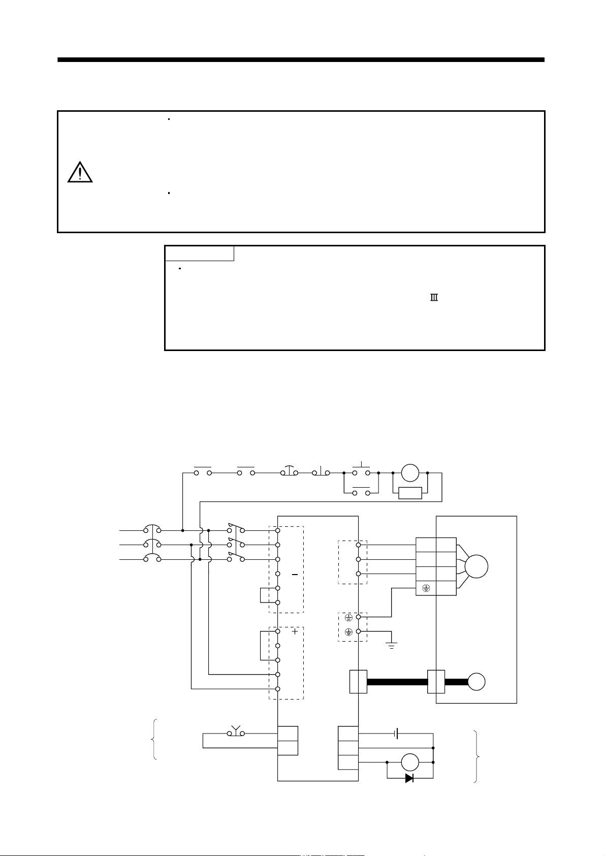
Wire the power supply/main circuit as shown below so that power is shut off and the servo-on command turned
off as soon as an alarm occurs, a servo forced stop is made valid, or a controller forced stop is made valid. A
no-fuse breaker (NFB) must be used with the input cables of the main circuit power supply.
(1) For 3-phase 200V to 230VAC power supply to MR-J3-10B to MR-J3-350B
EM1
NFB MC
L
1
L2
L
3
ALM RA1
P
1
P( )
DICOM
DOCOM
L
11
L21
N( )
D
C
U
V
W
(Note 1)
(Note 2)
CNP1
CNP3
PE
CNP2
U
V
W
2
3
4
1
M
Motor
Encoder
CN2
24VDC
(Note 3)
Encoder cable
(Note 6)
DOCOM
Forced stop
CN3CN3
OFF
Forced
stop
ON
MC
MC
SK
(Note 4)
Alarm
RA1
Controller
forced stop
RA2
Servo amplifier Servo motor
(Note 5)
Trouble
(Note 4)
(Note 5)
3-phase
200 to
230VAC
P
2