sh030051g.pdf - 第66页
3 - 11 3. SIGNALS AND WI RING Note 1 To prevent an electric shock, always connect the protective earth (PE) terminal (terminal mark ed ) of the se rvo amplifier to the protective earth (PE) of the control box. 2. Connect…
3 - 10
3. SIGNALS AND WIRING
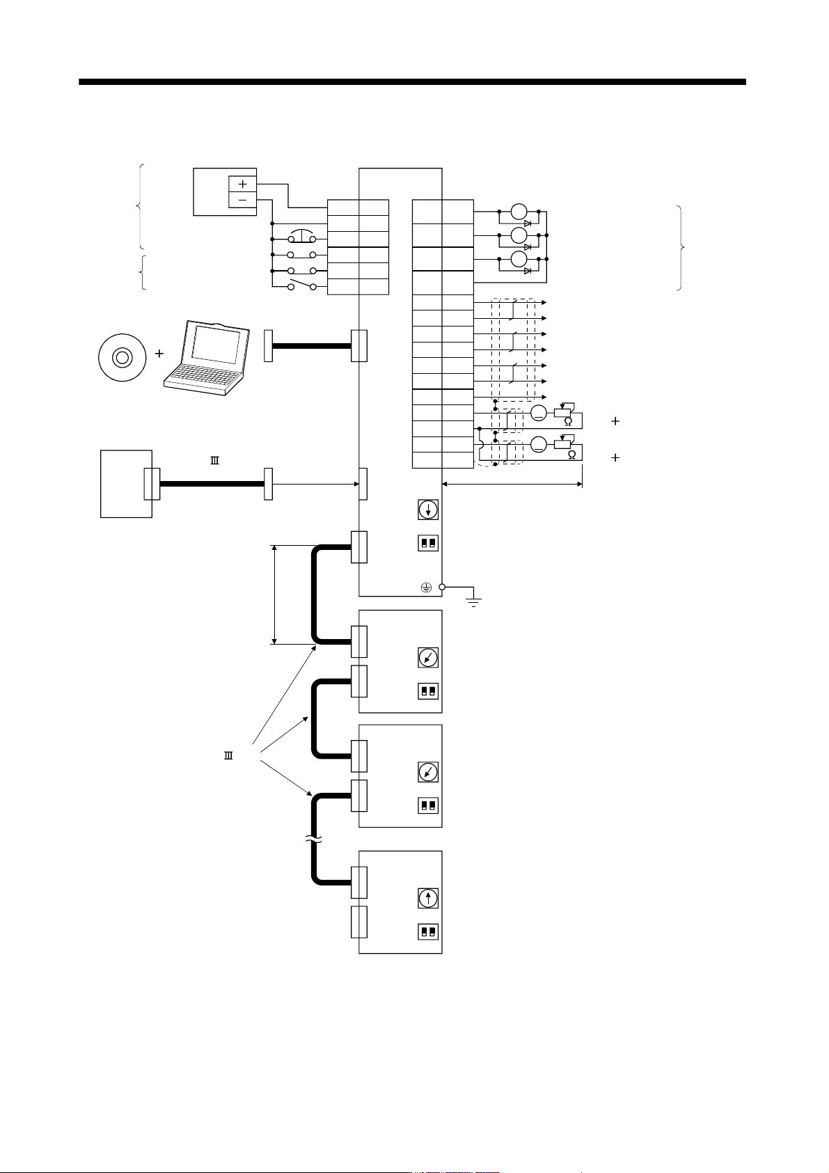
3.2 I/O signal connection example
13
9
15
10
6
16
7
17
2
12
19
CN3
Encoder Z-phase pulse
(differential line driver)
2m Max
(Note 12)
(Note 5)
MR Configurator
Personal
computer
Magnetic brake interlock
CN5
Servo amplifier
CN1A
Servo system
controller
USB cable
MR-J3USBCBL3M
(option)
Trouble (Note 11)
In-position
CN3
(Note 12)
CN1A
CN1B
MR-J3-B
(2 axis)
(Note 7)
(Note 9)
Cap
(Note 1)
CN1B
SW1
21
SW2
SW1
21
SW2
Between electrodes
Control common
(Note 8)
(Note 8)
CN1A
CN1B
MR-J3-B
(Note 7)
SW1
21
SW2
(Note 8)
CN1A
CN1B
MR-J3-B
(Note 7)
SW1
21
SW2
(Note 8)
24VDC
Power
supply
(Note 10)
(Note 3,4)Forced stop
(Note 14)
(3 axis)
(n axis)
(Note 6 )
SSCNET cable
(option)
(Note 6)
SSCNET cable
(option)
Analog monitor 2
Max. 1mA meter
both directions
Analog monitor 1
Max. 1mA meter
both directions
10k
Encoder B-phase pulse
(differential line driver)
Encoder A-phase pulse
(differential line driver)
A
A
10k
(Note 15)
RA3
RA2
RA1
DICOM
DOCOM
EM1
DI1
DI2
DI3
5
3
20
DICOM
MBR
INP
ALM
LA
LAR
LB
LBR
8LZ
18 LZR
11 LG
4MO1
1LG
14 MO2
Plate SD
(Note 2)
(Note 13,14)
Upper stroke limit (FLS)
Lower stroke limit (RLS)
Proximity dog (DOG)
3 - 11
3. SIGNALS AND WIRING
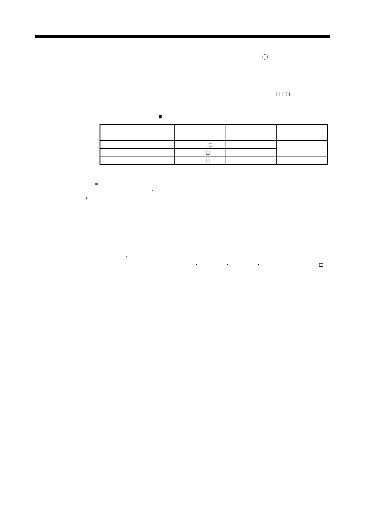
Note 1 To prevent an electric shock, always connect the protective earth (PE) terminal (terminal marked ) of the servo amplifier to the
protective earth (PE) of the control box.
2. Connect the diode in the correct direction. If it is connected reversely, the servo amplifier will be faulty and will not output
signals, disabling the forced stop (EM1) and other protective circuits.
3. If the controller does not have an forced stop (EM1) function, always install a forced stop switch (Normally closed).
4. When starting operation, always turn on the forced stop (EM1). (Normally closed contacts) By setting "
1 " in DRU
parameter No.PA04 of the drive unit, the forced stop (EM1) can be made invalid.
5. Use MRZJW3-SETUP 221E.
6. For the distance between electrodes of SSCNET
cable, refer to the following table.
Cable Cable model name Cable length
Distance between
electrodes
Standard code inside panel MR-J3BUS M 0.15m to 3m
20m
Standard cable outside panel MR-J3BUS M-A 5m to 20m
Long-distance cable MR-J3BUS M-B 30m to 50m 50m
7. The wiring of the second and subsequent axes is omitted.
8. Up to eight axes (n
1 to 8) may be connected. Refer to section 3.13 for setting of axis selection.
9. Make sure to put a cap on the unused CN1A
CN1B.
10. Supply 24VDC
10% 150mA current for interfaces from the outside. 150mA is the value applicable when all I/O signals are
used. The current capacity can be decreased by reducing the number of I/O points. Refer to section 3.7.2 (1) that gives the
current value necessary for the interface.
11. Trouble (ALM) turns on in normal alarm-free condition. When this signal is switched off (at occurrence of an alarm), the output
of the programmable controller should be stopped by the sequence program.
12. The pins with the same signal name are connected in the servo amplifier.
13. The signal can be changed by parameter No.PD07, PD08, PD09.
14. For the sink I/O interface. For the source I/O interface, refer to section 3.7.3.
15. Devices can be assigned for DI1
DI2 DI3 with controller setting. For devices that can be assigned, refer to the controller
instruction manual. The assigned devices are for the Q173DCPU
Q172DCPU Q173HCPU Q172HCPU and QD75MH .
3 - 12
3. SIGNALS AND WIRING
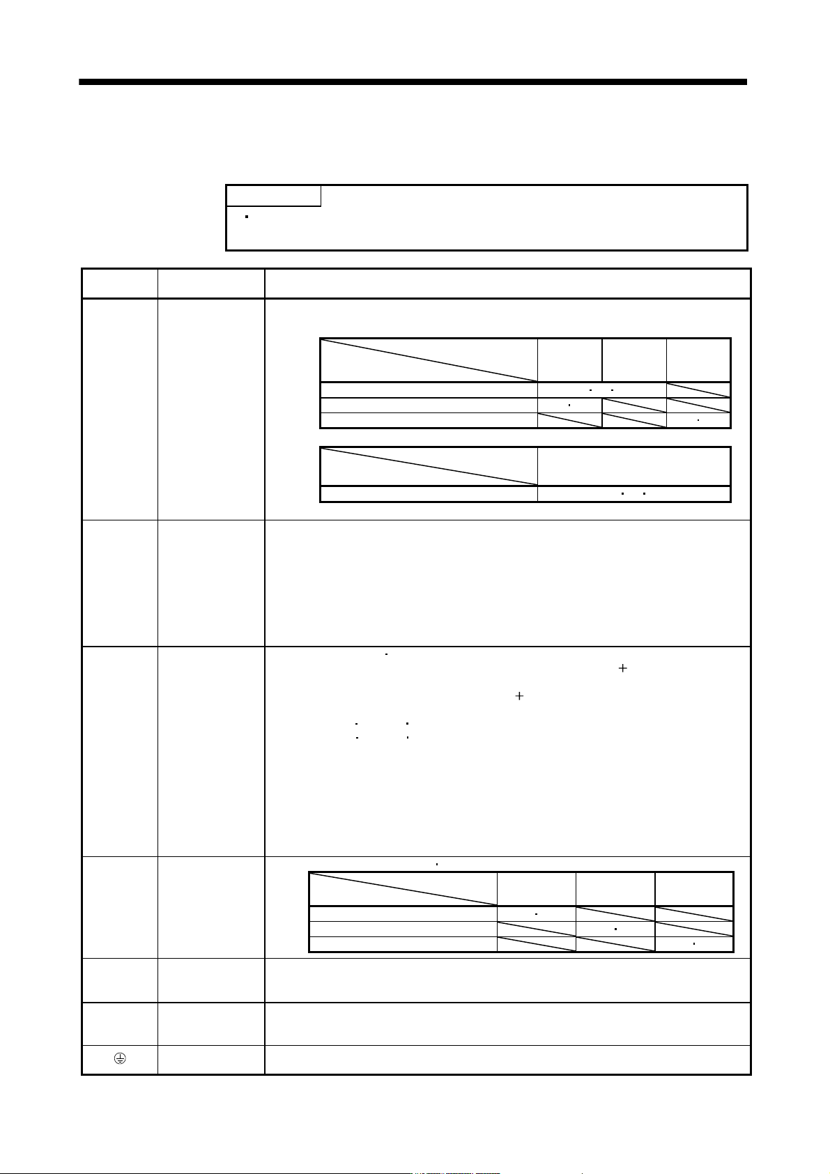
3.3 Explanation of power supply system
3.3.1 Signal explanations
POINT
For the layout of connector and terminal block, refer to outline drawings in
chapter 9.
Abbreviation
Connection target
(Application)
Description
L1
L
2
L
3
Main circuit power
supply
Supply the following power to L
1, L2, L3. For the 1-phase 200V to 230VAC power supply, connect
the power supply to L
1, L2, and keep L3 open.
Servo amplifier
Power supply
MR-J3-
10B to 70B
MR-J3-
100B to
22KB
MR-J3-
10B1 to
40B1
3-phase 200V to 230VAC, 50/60Hz L1 L2 L3
1-phase 200V to 230VAC, 50/60Hz L1 L2
1-phase 100V to 120VAC, 50/60Hz L1 L2
Servo amplifier
Power supply
MR-J3-60B4 to 22KB4
3-phase 380V to 480VAC, 50/60Hz L1 L2 L3
P1
P
2
Power factor
improving DC
reactor
1) MR-J3-700B or less
When not using the power factor improving DC reactor, connect P
1 and P2. (Factory-wired.)
When using the power factor improving DC reactor, disconnect P
1 and P2, and connect the
power factor improving DC reactor to P
1 and P2.
2) MR-J3-11KB(4) to 22KB(4)
MR-J3-11KB(4) to 22KB(4) do not have P
2.
When not using the power factor improving reactor, connect P
1 and P. (Factory-wired)
When using the power factor improving reactor, connect it to P and P
1.
Refer to section 11.13.
P
C
D
Regenerative
option
1) MR-J3-350B or less
MR-J3-200B4 or less
When using servo amplifier built-in regenerative resistor, connect P(
) and D. (Factory-
wired)
When using regenerative option, disconnect P(
) and D, and connect regenerative option to
P and C.
2) MR-J3-350B4
500B(4) 700B(4)
MR-J3-350B4
500B(4) 700B(4) do not have D.
When using servo amplifier built-in regenerative resistor, connect P and C. (Factory-wired)
When using regenerative option, disconnect P and C, and connect regenerative option to P
and C.
3) MR-J3-11KB(4) to 22KB(4)
MR-J3-11KB(4) to 22KB(4) do not have D.
When not using the power regenerative converter and the brake unit, make sure to connect
the regenerative option to P and C.
Refer to section 11.2 to 11.5.
L11
L
21
Control circuit
power supply
Supply the following power to L
11 L21.
Servo amplifier
Power supply
MR-J3-10B to
22KB
MR-J3-10B1 to
40B1
MR-J3-60B4 to
22KB4
1-phase 200V to 230VAC, 50/60Hz L11 L21
1-phase 100V to 120VAC, 50/60Hz L11 L21
1-phase 380V to 480VAC, 50/60Hz L11 L21
U
V
W
Servo motor power
Connect to the servo motor power supply terminals (U, V, W). During power-on, do not open or
close the motor power line. Otherwise, a malfunction or faulty may occur.
N
Return converter
Brake unit
When using the power regenerative converter/brake unit, connect it to P and N.
Do not connect to servo amplifier MR-J3-350B(4) or less.
For details, refer to section 11.3 to 11.5.
Protective earth
(PE)
Connect to the earth terminal of the servo motor and to the protective earth (PE) of the control
box to perform grounding.