sh030051g.pdf - 第171页
7 - 14 7. SPECIAL ADJUSTMENT FUNCTIONS 7.6.4 Gain changing operation This operation will be described b y way of setting exa mples. (1) When you choose changing by input device (a) Setting Parameter No. Abbreviation Name…
7 - 13
7. SPECIAL ADJUSTMENT FUNCTIONS
(1) Parameters No.PB06 to PB10
These parameters are the same as in ordinary manual adjustment. Gain changing allows the values of
ratio of load inertia moment to servo motor inertia moment, position loop gain, speed loop gain and speed
integral compensation to be changed.
(2) Gain changing ratio of load inertia moment to servo motor inertia moment (GD2B: parameter No.PB29)
Set the ratio of load inertia moment to servo motor inertia moment after changing. If the load inertia moment
ratio does not change, set it to the same value as ratio of load inertia moment to servo motor inertia moment
(parameter No.PB06).
(3) Gain changing position loop gain (parameter No.PB30), Gain changing speed loop gain (parameter
No.PB31), Gain changing speed integral compensation (parameter No.PB32)
Set the values of after-changing position loop gain, speed loop gain and speed integral compensation.
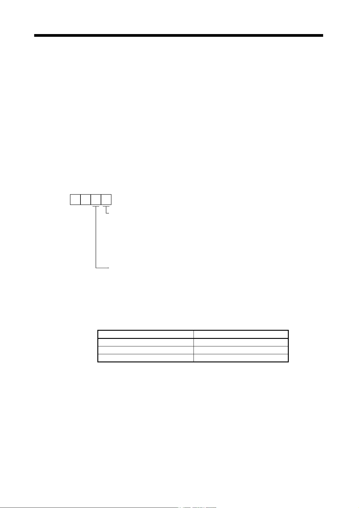
(4) Gain changing selection (parameter No.PB26)
Used to set the gain changing condition. Choose the changing condition in the first digit and second digit. If
you set "1" in the first digit here, you can use the control command from controller is valid for gain changing.
Gain changing selection
Under any of the following conditions, the gains
change on the basis of the parameter No.PB29 to
PB32 settings.
0: Invalid
1: Control command from controller is valid
2: Command frequency (Parameter No.PB27 setting)
3: Droop pulse value (Parameter No.PB27 setting)
4: Servo motor speed (Parameter No.PB27 setting)
00
Gain changing condition
0: Valid at more than condition (Valid with ON for control command from controller.)
1: Valid at less than condition (Valid with OFF for control command from controller.)
(5) Gain changing condition (parameter No.PB27)
When you selected "command frequency", "droop pulses" or "servo motor speed" in gain changing
selection (parameter No.PB26), set the gain changing level.
The setting unit is as follows.
Gain changing condition Unit
Command frequency kpps
Droop pulses pulse
Servo motor speed r/min
(6) Gain changing time constant (parameter No.PB28)
You can set the primary delay filter to each gain at gain changing. This parameter is used to suppress
shock given to the machine if the gain difference is large at gain changing, for example.
7 - 14
7. SPECIAL ADJUSTMENT FUNCTIONS
7.6.4 Gain changing operation
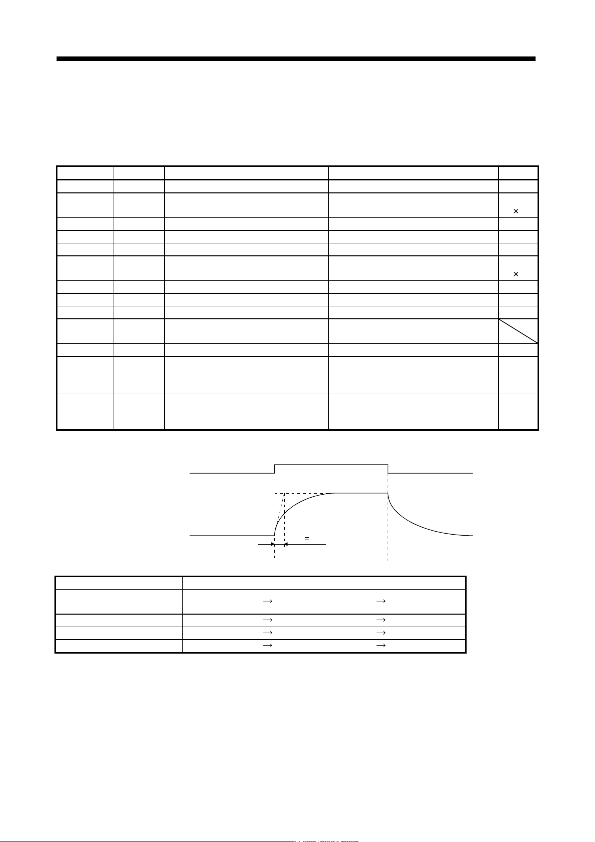
This operation will be described by way of setting examples.
(1) When you choose changing by input device
(a) Setting
Parameter No. Abbreviation Name Setting Unit
PB07 PG1 Model loop gain 100 rad/s
PB06 GD2
Ratio of load inertia moment to servo motor
inertia moment
4.0
Multiplier
(
1)
PB08 PG2 Position loop gain 120 rad/s
PB09 VG2 Speed loop gain 3000 rad/s
PB10 VIC Speed integral compensation 20 Ms
PB29 GD2B
Gain changing ratio of load inertia moment
to servo motor inertia moment
10.0
Multiplier
(
1)
PB30 PG2B Gain changing position loop gain 84 rad/s
PB31 VG2B Gain changing speed loop gain 4000 rad/s
PB32 VICB Gain changing speed integral compensation 50 ms
PB26 CDP Gain changing selection
0001
(Changed by ON/OFF of input device)
PB28 CDT Gain changing time constant 100 ms
PB33 VRF1B
Gain changing vibration suppression control
vibration frequency setting
Used to set the value of the after-changing
vibration suppression control vibration
frequency setting.
Hz
PB34 VRF2B
Gain changing vibration suppression control
resonance frequency setting
Used to set the value of the after-changing
vibration suppression control resonance
frequency setting.
Hz
(b) Changing operation
OFF
ON
OFF
Control command
of controller
Change of
each gain
Before-changing gain
After-changing gain
CDT 100ms
Model loop gain 1 100
Ratio of load inertia moment
to servo motor inertia moment
4.0
10.0 4.0
Position loop gain 120 84 120
Speed loop gain 3000 4000 3000
Speed integral compensation 20 50 20
7 - 15
7. SPECIAL ADJUSTMENT FUNCTIONS
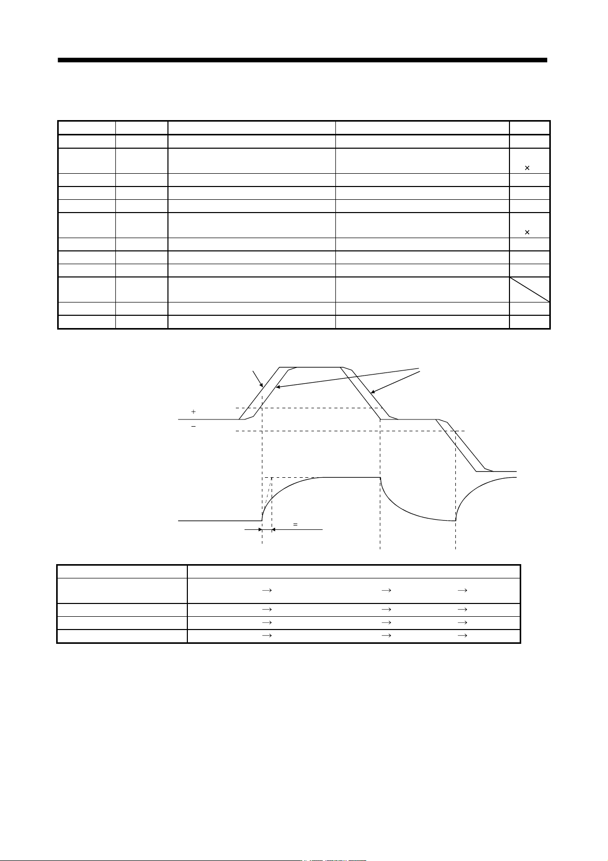
(2) When you choose changing by droop pulses
(a) Setting
Parameter No. Abbreviation Name Setting Unit
PB07 PG1 Model loop gain 100 rad/s
PB06 GD2
Ratio of load inertia moment to servo motor
inertia moment
4.0
Multiplier
(
1)
PB08 PG2 Position loop gain 120 rad/s
PB09 VG2 Speed loop gain 3000 rad/s
PB10 VIC Speed integral compensation 20 ms
PB29 GD2B
Gain changing ratio of load inertia moment to
servo motor inertia moment
10.0
Multiplier
(
1)
PB30 PG2B Gain changing position loop gain 84 rad/s
PB31 VG2B Gain changing speed loop gain 4000 rad/s
PB32 VICB Gain changing speed integral compensation 50 ms
PB26 CDP Gain changing selection
0003
(Changed by droop pulses)
PB27 CDS Gain changing condition 50 pulse
PB28 CDT Gain changing time constant 100 ms
(b) Changing operation
CDT 100ms
0
Droop pulses [pulses]
Change of each gain
CDS
CDS
Before-changing gain
After-changing gain
Command pulse
Droop pulses
Model loop gain 100
Ratio of load inertia moment
to servo motor inertia moment
4.0
10.0 4.0 10.0
Position loop gain 120 84 120 84
Speed loop gain 3000 4000 3000 4000
Speed integral compensation 20 50 20 50