sh030051g.pdf - 第362页
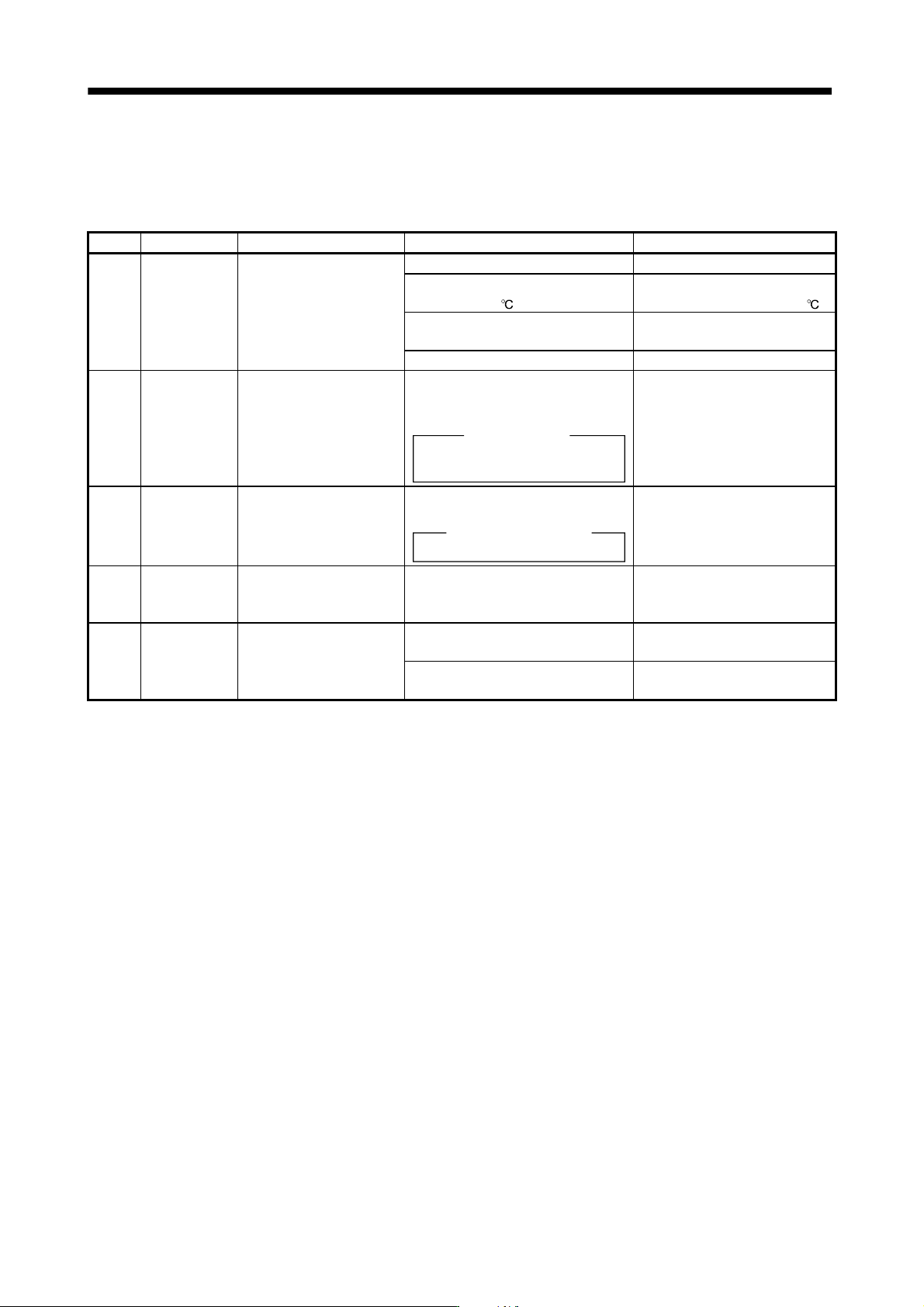
13 - 61 13. SERVO AMPLIFIERS WI TH A LARGE CAPACITY ( 30k TO 55kW ) (3) Remedies for warnings Continuing operation in an alarm occurrence status ma y result in an alarm or disable proper op eration. Eliminate the cause o…
13 - 60
13. SERVO AMPLIFIERS WITH A LARGE CAPACITY
(
30k TO 55kW
)
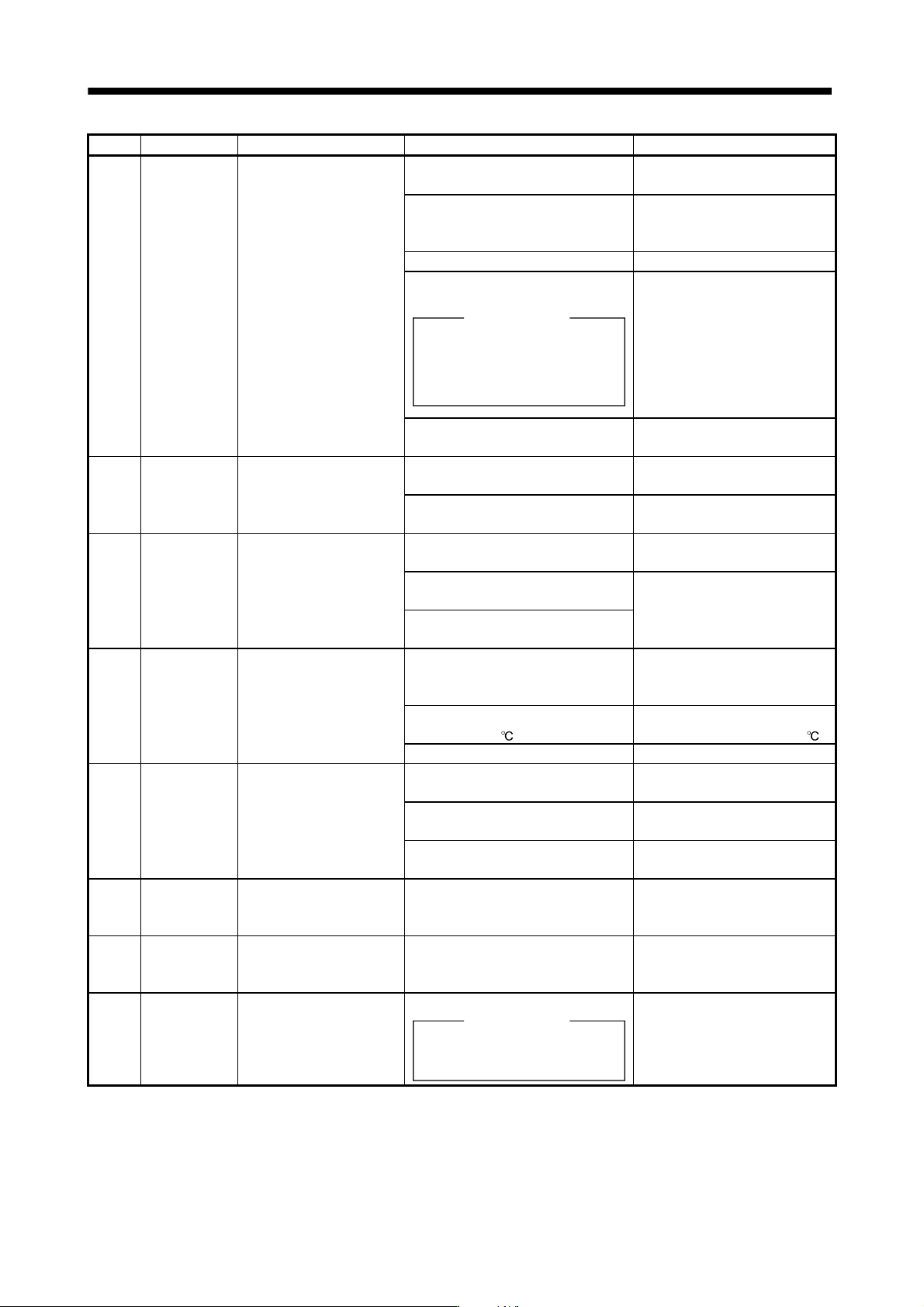
Display Name Definition Cause Action
A.38 MC drive circuit
error
Magnetic contactor drive
circuit error
(When the magnetic
contactor is turned on: the
main circuit power supply is
not turned on within two
seconds after the servo-on
of the drive unit.
When the magnetic
contactor is opened: the
main circuit power supply is
turned on although the
magnetic contactor is
opened.)
1. Wrong connection of the magnetic
contactor.
Review the wiring.
2. Parameters specifying whether to
use/not use the magnetic contactor
do not match the configuration.
Set parameter No.PA02 correctly.
3. Magnetic contactor failed. Change the magnetic contactor.
4. Magnetic contactor drive circuit
faulty.
Checking method
Check the output of magnetic
contactor control connector (CNP1) .
Power supply voltage is applied to
this connector. Take care to avoid an
electric shock at connecting.
Change the converter unit.
5. Mismatch of an external sequence. Review the power-on sequence.
(Refer to section 3.3.2.)
A.39 Open phase Power supply error 1. Any of L
1
, L
2
and L
3
is disconnected.
Or, open.
Review the wiring.
2. Failure of the part in the converter
unit.
Change the converter unit.
A.3A Inrush current
suppressor
circuit error
Inrush current suppressor
circuit error
1. Power-on/off was repeated with high
frequency.
Review operation pattern.
2. Inrush current suppressor resistance
overheated.
Change the converter unit.
3. Inrush current suppressor circuit
faulty.
A.45 Main circuit
device
overheat
Main circuit device
overheat.
1. The power supply was turned on and
off continuously by overloaded
status.
Review operation pattern.
2. Ambient temperature of converter
unit is over 55
.
Review environment so that
ambient temperature is 0 to 55 .
3. Converter unit faulty. Change the converter unit.
A.47 Cooling fan
alarm
The cooling fan of the
converter unit stopped, or its
speed decreased to or
below the alarm level.
1. Cooling fan life expiration. (Refer to
section 2.6.)
Change the cooling fan of the
converter unit.
2. Foreign matter caught in the cooling
fan stopped rotation.
Remove the foreign matter.
3. The power supply of the cooling fan
failed.
Change the converter unit.
A.50 Overload 1 Load exceeded overload
protection characteristic of
converter unit.
Converter unit is used in excess of its
continuous output current.
1. Reduce load.
2. Review operation pattern.
A.51 Overload 2 Load exceeded overload
protection characteristic of
converter unit.
Converter unit is used in excess of its
output current for a short time.
Review operation pattern of a
drive unit.
(Note)
888
Watchdog CPU/parts fault Failure of the part in the converter unit.
Checking method
Alarm (888) occurs if power is
switched on after connectors
disconnected.
Change the converter unit.
Note. At power-on, "888" appears instantaneously, but it is not an error.
13 - 61
13. SERVO AMPLIFIERS WITH A LARGE CAPACITY
(
30k TO 55kW
)
(3) Remedies for warnings
Continuing operation in an alarm occurrence status may result in an alarm or disable proper operation.
Eliminate the cause of the warning according to this section. The warning displayed will disappear when the
cause of its occurrence is resolved.
Display Name Definition Cause Action
A.91 Overheat
warning
The temperature of the fin
exceeded the warning level.
1. Operated in the overloaded status. Review operation pattern.
2. Ambient temperature of converter
unit is over 55
.
Review environment so that
ambient temperature is 0 to 55 .
3. Used beyond the specifications of
close mounting.
Use within the range of
specifications.
4. Converter unit faulty. Change the converter unit.
A.E0 Excessive
regenerative
load warning
There is a possibility that
regenerative power may
exceed permissible
regenerative power of
regenerative option.
Regenerative power increased to 85%
or more of permissible regenerative
power of regenerative option.
Checking method
Call the status display and check the
regenerative load ratio.
1. Reduce frequency of
positioning.
2. Change regenerative option for
the one with larger capacity.
3. Reduce load.
A.E1 Overload
warning
There is a possibility that
overload alarm 1 or 2 may
occur.
Load increased to 85% or more of
overload alarm 1 or 2 occurrence level.
Cause, checking method
Refer to A.50, 51.
Refer to A.50, A.51.
A.E6 Converter
forced stop
warning
EM1 is off. External forced stop was made valid.
(EM1 was turned off.)
Ensure safety and deactivate
forced stop.
A.E8 Cooling fan
speed
reduction
warning
The speed of the converter
unit cooling fan decreased
to or below the warning
level.
1. Cooling fan life expiration. (Refer to
section 2.6.)
Change the cooling fan of the
converter unit.
2. The power supply of the cooling fan
failed.
Change the converter unit.
(4) Clearing the alarm history
You can clear the alarm numbers stored in the alarm history of the alarm mode. To ensure that you can
control the alarms that will occur after regular operation, make this setting before starting regular operation
to clear the alarm history.
After setting "0001" in parameter No.PA09, switch power off once. Switching it on again clears the alarm
history. At this time, the parameter No.PA09 setting returns to "0000".
13 - 62
13. SERVO AMPLIFIERS WITH A LARGE CAPACITY
(
30k TO 55kW
)
13.6.2 Drive unit
POINT
Explanation made in this section is exclusively for the driver unit.
Other troubleshooting is the same as that for servo amplifiers with 22kW or
less. Refer to chapter 8.
As soon as an alarm occurs, make the Servo off status and interrupt the main
circuit power.
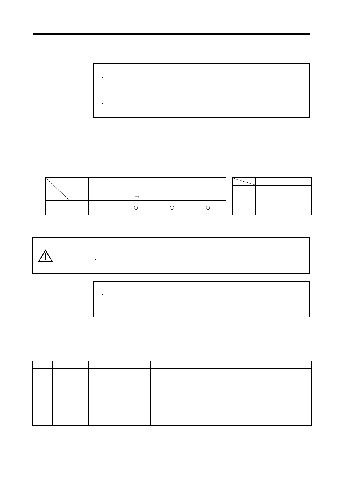
(1) Alarms and warning list
When a fault occurs during operation, the corresponding alarm or warning is displayed. If any alarm or
warning has occurred, refer to (2) or (3) of this section and take the appropriate action. When an alarm
occurs, the ALM turns OFF.
After its cause has been removed, the alarm can be deactivated in any of the methods marked in the alarm
deactivation column. The alarm is automatically canceled after removing the cause of occurrence.
Display Name
Alarm deactivation
Display Name
Power
OFF
ON
Error reset CPU reset
Alarms
9C
Converter
warning
Alarms 1B
Converter
alarm
E9
Main circuit off
warning
(2) Remedies for alarms
CAUTION
When any alarm has occurred, eliminate its cause, ensure safety, then reset the
alarm, and restart operation. Otherwise, injury may occur.
As soon as an alarm occurs, mark servo-off and power off the main circuit and
control circuit.
POINT
The alarm can be deactivated by switching power off, then on or by the error
reset command CPU reset from the servo system controller. For details, refer
to (1) of this section.
When an alarm occurs, the trouble (ALM) switches off and the dynamic brake is operated to stop the servo
motor. At this time, the display indicates the alarm No.
The servo motor comes to a stop. Remove the cause of the alarm in accordance with this section. MR
Configurator may be used to refer to the cause.
Display Name Definition Cause Action
1B Converter
alarm
An alarm occurred in the
converter unit during servo
on.
1. An alarm occurred in the converter
unit during servo on.
Check the alarm of the converter
unit, and take the action following
the remedies for alarms of the
converter unit. (Refer to section
13.6.1 (2).)
2. The protection coordination cable or
terminal connector is not correctly
connected.
Connect correctly.