sh030051g.pdf - 第140页
5 - 23 5. PARAMETERS Setting Output item Description Setting Output item Description 6 Droop pulses (Note 1) ( 10V/100 pulses) 100[pulse] CW direction CCW direct ion 100[pulse] 0 10[V] -10[V] 7 Droop pulses (Note 1) ( 10…
5 - 22
5. PARAMETERS
5.3.3 Analog monitor
The servo status can be output to two channels in terms of voltage. The servo status can be monitored using
an ammeter.
(1) Setting
Change the following digits of parameter No.PC09, PC10.
Analog monitor (MO1) output selection
(Signal output to across MO1-LG)
Analog monitor (MO2) output selection
(Signal output to across MO2-LG)
000
000
Parameter No.PC09
Parameter No.PC10
Parameters No.PC11 and PC12 can be used to set the offset voltages to the analog output voltages. The
setting range is between
999 and 999mV.
Parameter No. Description Setting range [mV]
PC11 Used to set the offset voltage for the analog monitor 1 (MO1).
999 to 999
PC12 Used to set the offset voltage for the analog monitor 2 (MO2).
(2) Set content
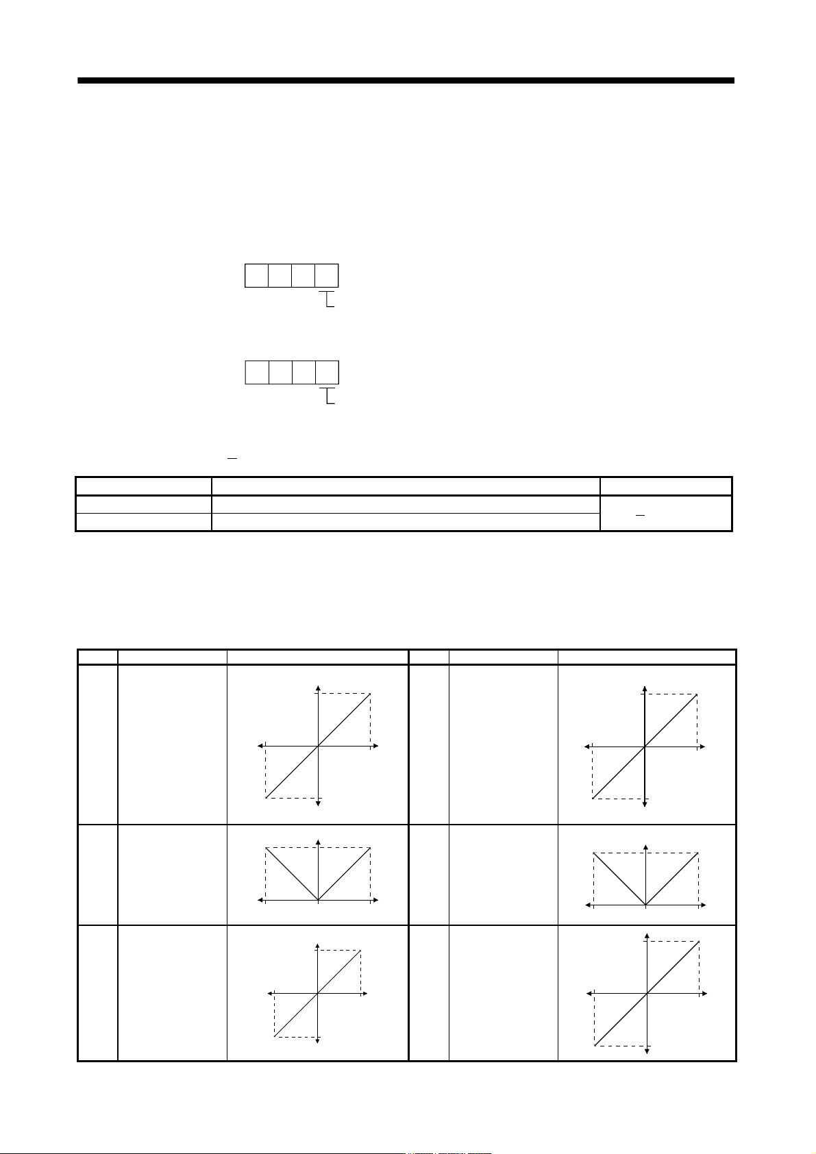
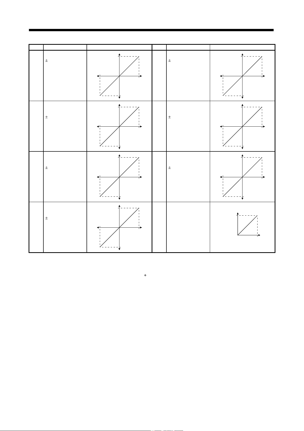
The servo amplifier is factory-set to output the servo motor speed to analog monitor 1 (MO1) and the torque
to analog monitor (MO2). The setting can be changed as listed below by changing the parameter No.PC14
and PC12 value.
Refer to (3) for the measurement point.
Setting Output item Description Setting Output item Description
0 Servo motor speed
Max. speed
CW direction
CCW direction
Max. speed
0
8[V]
-8[V]
1 Torque (Note 3)
Max. torque
Driving in CW
direction
Driving in CCW
direction
Max. torque
0
8[V]
-8[V]
2 Servo motor speed
CCW direction
Max. speed Max. speed0
8[V]
CW direction
3 Torque (Note 3)
Driving in CCW
direction
Max. torque
Max. torque0
8[V]
Driving in CW
direction
4 Current command
Max. current command
(Max. torque command)
C
W
d
ir
ec
ti
o
n
CCW direction
Max. current command
(Max. torque command)
0
8[V]
-8[V]
5 Speed command
Max. speed
CW direction
CCW direction
Max. speed
0
8[V]
-8[V]
5 - 23
5. PARAMETERS
Setting Output item Description Setting Output item Description
6 Droop pulses (Note 1)
(
10V/100 pulses)
100[pulse]
CW direction
CCW direction
100[pulse]
0
10[V]
-10[V]
7 Droop pulses (Note 1)
(
10V/1000 pulses)
1000[pulse]
CW direction
CCW direction
1000[pulse]
0
10[V]
-10[V]
8 Droop pulses
(Note 1)
(
10V/10000 pulses)
10000[pulse]
CW direction
CCW direction
10000[pulse]
0
10[V]
-10[V]
9 Droop pulses
(Note 1)
(
10V/100000 pulses)
100000[pulse]
CW direction
CCW direction
100000[pulse]
0
10[V]
-10[V]
A Feedback position
(Note 1,2)
(
10V/1 Mpulses)
1M[pulse]
CW direction
CCW direction
1M[pulse]
0
10[V]
-10[V]
B Feedback position
(Note 1,2)
(
10V/10 Mpulses)
10M[pulse]
CW direction
CCW direction
10M[pulse]
0
10[V]
-10[V]
C Feedback position
(Note 1,2)
(
10V/100 Mpulses)
100M[pulse]
CW direction
CCW direction
100M[pulse]
0
10[V]
-10[V]
D Bus voltage (Note 4)
400[V]
0
8[V]
Note 1. Encoder pulse unit.
2. Available in position control mode
3. Outputs 8V at the maximum torque.
4. For 400V class servo amplifier, the bus voltage becomes
8V/800V.
5 - 24
5. PARAMETERS
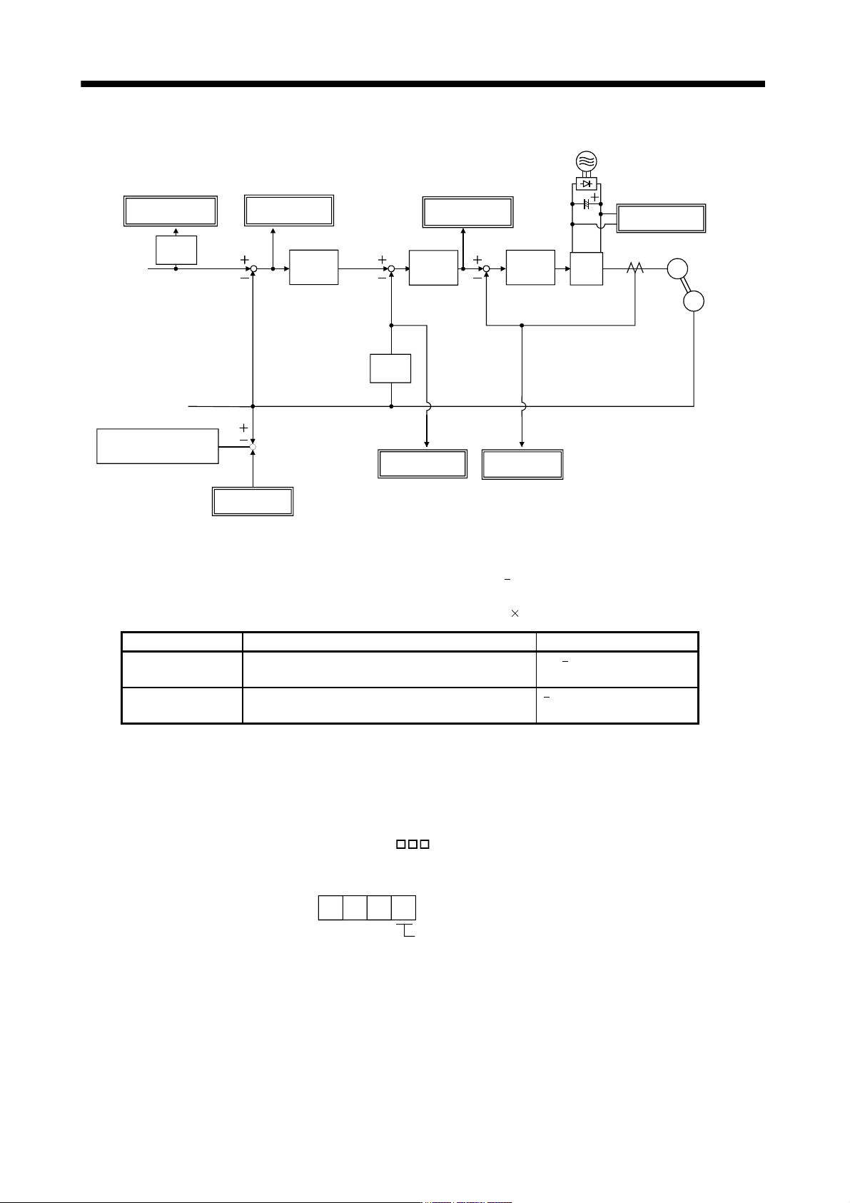
(3) Analog monitor block diagram
PWM M
Feedback
position
Current
control
Speed
control
Current
command
Position
control
Droop pulse
Differ-
ential
Speed
command
Bus voltage
Speed
command
Current feedback
Position feedback
Servo Motor
speed
Current encoder
Servo Moto
r
Encoder
Torque
Position
command
received
from a
controller
Feedback position
standard position (Note)
Differ-
ential
Position feedbac
k
data returned to
a controller
Note. The feedback position is output based on the position data passed between servo system controller and servo amplifier. The
parameter number No.PC13/PC14 can set up the standard position of feedback position that is output to analog monitor in order
to adjust the output range of feedback position. The setting range is between
99999999 and 99999999 pulses.
Standard position of feedback position = Parameter No.PC14 setting value 10000 + Parameter No.PC13 setting value
Parameter No. Description Setting range
PC13
Sets the lower-order four digits of the standard position
of feedback position
9999 to 9999 [pulse]
PC14
Sets the higher-order four digits of the standard position
of feedback position
9999 to 9999 [10000pulses]
5.3.4 Alarm history clear
The servo amplifier stores one current alarm and five past alarms from when its power is switched on first. To
control alarms which will occur during operation, clear the alarm history using parameter No.PC21 before
starting operation.
Clearing the alarm history automatically returns to "
0 ".
After setting, this parameter is made valid by switch power from OFF to ON.
Alarm history clear
0: Invalid (not cleared)
1: Valid (cleared)
0
00
Parameter No.PC21