sh030051g.pdf - 第241页
11 - 36 11. OPTIONS AND AUXILI ARY EQUIPMENT 11.3.3 Connection exampl e POINT Connecting PR terminal of the brake unit to P terminal of the servo amplifier results in brake unit malfunction. Always connect the PR termina…
11 - 35
11. OPTIONS AND AUXILIARY EQUIPMENT
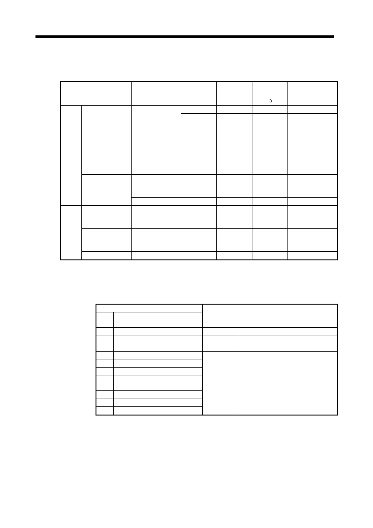
11.3.1 Selection
Use a combination of servo amplifier, brake unit and resistor unit listed below.
Brake unit Resistor unit
Number of
connected
units
Permissible
continuous
power [kW]
Total
resistance
[
]
Applicable servo
amplifier
200V FR-BU2-15K FR-BR-15K 1 0.99 8 MR-J3-500B (Note)
class 2 (parallel) 1.98 4 MR-J3-500B
MR-J3-700B
MR-J3-11KB
MR-J3-15KB
FR-BU2-30K FR-BR-30K 1 1.99 4 MR-J3-500B
MR-J3-700B
MR-J3-11KB
MR-J3-15KB
FR-BU2-55K FR-BR-55K 1 3.91 2 MR-J3-11KB
MR-J3-15KB
MR-J3-22KB
MT-BR5-55K 1 5.5 2 MR-J3-22KB
400V
class
FR-BU2-H30K FR-BR-H30K 1 1.99 16 MR-J3-500B4
MR-J3-700B4
MR-J3-11KB4
FR-BU2-H55K FR-BR-H55K 1 3.91 8 MR-J3-11KB4
MR-J3-15KB4
MR-J3-22KB4
FR-BU2-H75K MT-BR5-H75K 1 7.5 6.5 MR-J3-22KB4
11.3.2 Brake unit parameter setting
Normally, when using the FR-BU2-(H), changing parameters is not necessary. Whether a parameter can be
changed or not is listed below.
Parameter
Change
possible/
impossible
Remarks
No. Name
0 Brake mode switchover Impossible Do not change the parameter.
1 Monitor display data selection Possible Refer to the FR-BU2-(H) Brake Unit
Instruction Manual.
2 Input terminal function selection 1 Impossible Do not change the parameter.
3 Input terminal function selection 2
77 Parameter write selection
78 Cumulative energization time
carrying-over times
CLr Parameter clear
ECL Alarm history clear
C1 For manufacturer setting
11 - 36
11. OPTIONS AND AUXILIARY EQUIPMENT
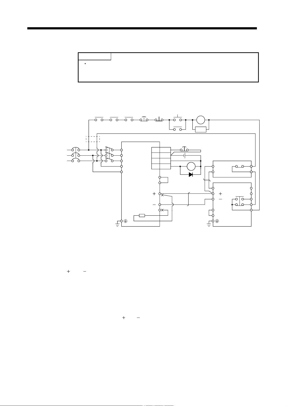
11.3.3 Connection example
POINT
Connecting PR terminal of the brake unit to P terminal of the servo amplifier
results in brake unit malfunction. Always connect the PR terminal of the brake
unit to the PR terminal of the resistor unit.
(1) Combination with FR-BR-(H) resistor unit
(a) When connecting a brake unit to a servo amplifier
NFB
RA1
24VDC
ALM
RA1
Servo motor
thermal relay
RA2
RA1
(Note 8)
(Note 1)
Power
supply
N/
P/
BUE
SD
PR
B
C
A
SD
MSG
(Note 4)
(Note 7)
3
10
EM1
DOCOM
DICOM
ALM
P
1
P2
P( )
N( )
C
FR-BU2-(H)
FR-BR-(H)
Servo amplifier
P
PR
TH2
TH1
(Note 6)
MC
(Note 5)
(Note 3)
(Note 2)
(Note 9)
L1
L
2
L
3
L
11
L21
20
15
CN3
(Note 10)
EM1
MC
SK
MC
ON
OFF
Controller
forced stop
RA3
Note 1. For power supply specifications, refer to section 1.3.
2. For the servo amplifier of 5k and 7kW, always disconnect the lead of built-in regenerative resistor, which is connected to the P
and C terminals. For the servo amplifier of 11k to 22kW, do not connect a supplied regenerative resistor to the P and C
terminals.
3. Always connect P
1 and P2 terminals (P1 and P for the servo amplifier of 11k to 22kW) (Factory-wired). When using the power
factor improving DC reactor, refer to section 11.13.
4. Connect the P/
and N/ terminals of the brake unit to a correct destination. Wrong connection results in servo amplifier and
brake unit malfunction.
5. For 400VAC class, a step-down transformer is required.
6. Contact rating: 1b contact, 110VAC_5A/220VAC_3A
Normal condition: TH1-TH2 is conducting. Abnormal condition: TH1-TH2 is not conducting.
7. Contact rating: 230VAC_0.3A/30VDC_0.3A
Normal condition: B-C is conducting/A-C is not conducting. Abnormal condition: B-C is not conducting/A-C is conducting.
8. For the servo amplifier of 11kW or more, connect the thermal relay censor of the servo amplifier.
9. Do not connect more than one cable to each P(
) to N( ) terminals of the servo amplifier.
10. Always connect BUE and SD terminals (Factory-wired).
11 - 37
11. OPTIONS AND AUXILIARY EQUIPMENT
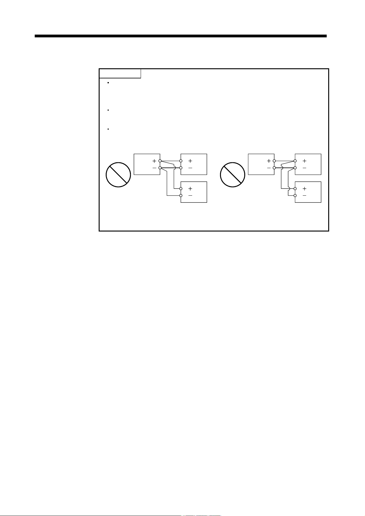
(b) When connecting two brake units to a servo amplifier
POINT
To use brake units with a parallel connection, use two sets of FR-BU2 brake
unit. Combination with other brake unit results in alarm occurrence or
malfunction.
Always connect the master and slave terminals (MSG and SD) of the two
brake units.
Do not connect the servo amplifier and brake units as below. Connect the
cables with a terminal block to distribute as indicated in this section.
N/
P/
Brake unit
Servo amplifier
P ( )
N ( )
N/
P/
Brake unit
Connecting two cables to
P and N terminals
N/
P/
Brake unit
Servo amplifier
P ( )
N ( )
N/
P/
Brake unit
Passing wiring