sh030051g.pdf - 第126页
5 - 9 5. PARAMETERS (1) For output pulse designation Set " 0 " (initial value) in parameter No.PC03. Set the number of pulses per servo moto r revolution. Output pulse set value [pulses/rev ] For instance, set …
5 - 8
5. PARAMETERS
5.1.8 Selection of servo motor rotation direction
Parameter
Initial value Unit Setting range
No. Symbol Name
PA14 *POL Rotation direction selection 0 0 1
POINT
This parameter is made valid when power is switched off, then on after
setting, or when the controller reset has been performed.
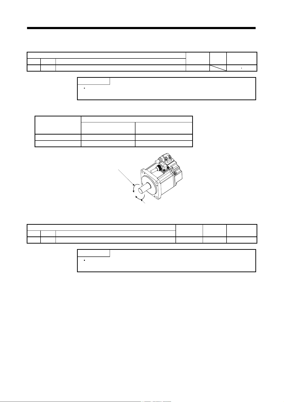
Select servo motor rotation direction relative.
Parameter No.PA14
setting
Servo motor rotation direction
When positioning address
increases
When positioning address
decreases
0 CCW CW
1 CW CCW
Forward rotation (CCW)
Reverse rotation (CW)
5.1.9 Encoder output pulse
Parameter
Initial value Unit Setting range
No. Symbol Name
PA15 *ENR Encoder output pulse 4000 pulse/rev 1 to 65535
POINT
This parameter is made valid when power is switched off, then on after
setting, or when the controller reset has been performed.
Used to set the encoder pulses (A-phase, B-phase) output by the servo amplifier.
Set the value 4 times greater than the A-phase or B-phase pulses.
You can use parameter No.PC03 to choose the output pulse setting or output division ratio setting.
The number of A/B-phase pulses actually output is 1/4 times greater than the preset number of pulses.
The maximum output frequency is 4.6Mpps (after multiplication by 4). Use this parameter within this range.

5 - 9
5. PARAMETERS
(1) For output pulse designation
Set "
0 " (initial value) in parameter No.PC03.
Set the number of pulses per servo motor revolution.
Output pulse
set value [pulses/rev]
For instance, set "5600" to Parameter No.PA15, the actually output A/B-phase pulses are as indicated
below.
4
5600
A B-phase output pulses 1400[pulse]
(2) For output division ratio setting
Set "
1 " in parameter No.PC03.
The number of pulses per servo motor revolution is divided by the set value.
Output pulse
[pulses/rev]
Resolution per servo motor revolution
Set value
For instance, set "8" to Parameter No.PA15, the actually output A/B-phase pulses are as indicated below.
A
B-phase output pulses 8192[pulse]
8
262144
4
1
5 - 10
5. PARAMETERS
5.2 Gain/filter parameters (No.PB
)
POINT
Parameter whose symbol is preceded by * is made valid with the following
conditions.
* : Set the parameter value, switch power off once after setting, and then
switch it on again, or perform the controller reset.
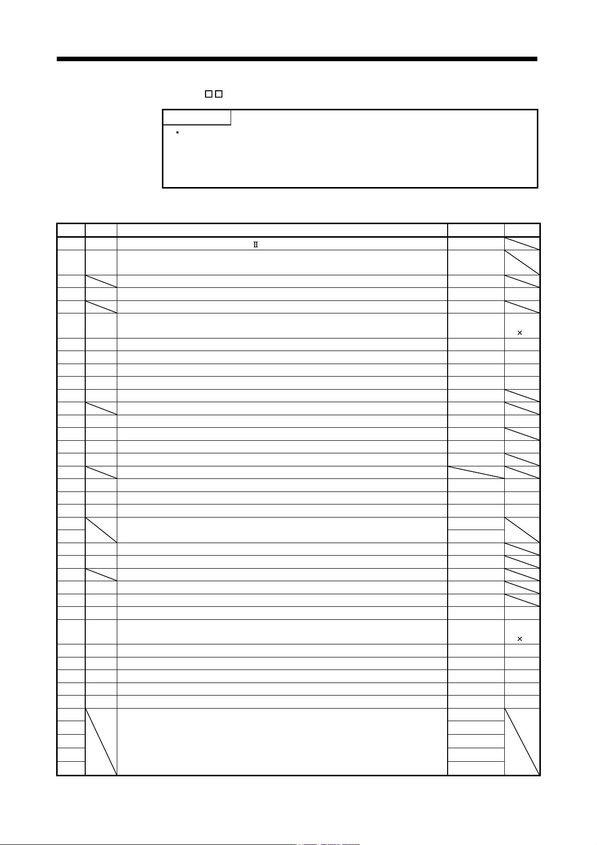
5.2.1 Parameter list
No. Symbol Name Initial value Unit
PB01 FILT Adaptive tuning mode (Adaptive filter ) 0000h
PB02 VRFT
Vibration suppression control tuning mode
(advanced vibration suppression control)
0000h
PB03 For manufacturer setting 0
PB04 FFC Feed forward gain 0 %
PB05 For manufacturer setting 500
PB06 GD2 Ratio of load inertia moment to servo motor inertia moment 7.0
Multiplier
(
1)
PB07 PG1 Model loop gain 24 rad/s
PB08 PG2 Position loop gain 37 rad/s
PB09 VG2 Speed loop gain 823 rad/s
PB10 VIC Speed integral compensation 33.7 ms
PB11 VDC Speed differential compensation 980
PB12 For manufacturer setting 0
PB13 NH1 Machine resonance suppression filter 1 4500 Hz
PB14 NHQ1 Notch shape selection 1 0000h
PB15 NH2 Machine resonance suppression filter 2 4500 Hz
PB16 NHQ2 Notch shape selection 2 0000h
PB17 Automatic setting parameter
PB18 LPF Low-pass filter setting 3141 rad/s
PB19 VRF1 Vibration suppression control vibration frequency setting 100.0 Hz
PB20 VRF2 Vibration suppression control resonance frequency setting 100.0 Hz
PB21
For manufacturer setting 0.00
PB22 0.00
PB23 VFBF Low-pass filter selection 0000h
PB24 *MVS Slight vibration suppression control selection 0000h
PB25 For manufacturer setting 0000h
PB26 *CDP Gain changing selection 0000h
PB27 CDL Gain changing condition 10
PB28 CDT Gain changing time constant 1 ms
PB29 GD2B Gain changing ratio of load inertia moment to servo motor inertia moment
7.0
Multiplier
(
1)
PB30 PG2B Gain changing position loop gain 37 rad/s
PB31 VG2B Gain changing speed loop gain 823 rad/s
PB32 VICB Gain changing speed integral compensation 33.7 ms
PB33 VRF1B Gain changing vibration suppression control vibration frequency setting 100.0 Hz
PB34 VRF2B Gain changing vibration suppression control resonance frequency setting 100.0 Hz
PB35
For manufacturer setting 0.00
PB36 0.00
PB37 100
PB38 0.0
PB39 0.0