sh030051g.pdf - 第385页
13 - 84 13. SERVO AMPLIFIERS WI TH A LARGE CAPACITY ( 30k TO 55kW ) 13.9.5 No-fuse breakers, fuses, magn etic contactors. Always use one no-fuse breakers and one magnetic contactor with one drive unit. Converter unit Dri…
13 - 83
13. SERVO AMPLIFIERS WITH A LARGE CAPACITY
(
30k TO 55kW
)
(1) When using the 600V Polyvinyl chloride insulated wire (IV wire)
Selection example of wire size when using IV wires is indicated below.
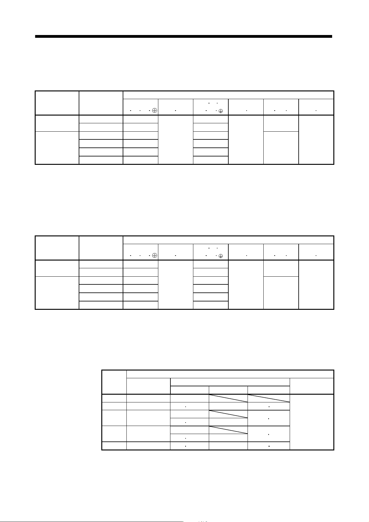
Table 13.4 Wire size selection example 1 (IV wire)
Converter unit
(Note 2)
Drive unit
Wires[mm
2
] (Note 1, 3)
1)
L
1
L
2
L
3
2)
L
11
L
21
3) U
V W
P
1
P
2
4)
P
2
C
5)
BU BV BW
6)
OHS1 OHS2
MR-J3-CR55K
MR-J3-DU30KB 50(AWG1/0): d 60(AWG2/0): d
2(AWG14)
MR-J3-DU37KB 60(AWG2/0): d (Note 4)
MR-J3-DU30KB4 22(AWG4): b
2(AWG14)
30(AWG2): c
5.5(AWG10): a
1.25(AWG16)
MR-J3-CR55K4
MR-J3-DU37KB4 30(AWG2): c 38(AWG2): c
1.25(AWG16)
MR-J3-DU45KB4 38(AWG2): c 50(AWG1/0): d
MR-J3-DU55KB4 50(AWG1/0): d 60(AWG2/0): d
Note 1. Alphabets in the table indicate crimping tools. For crimping terminals and applicable tools, refer to (3) in this section.
2. When connecting to the terminal block, be sure to use the screws which are provided with the terminal block.
3. For the servo motor with a cooling fan.
4. Wires are selected based on the highest rated current among combining servo motors.
(2) When using the 600V Grade heat-resistant polyvinyl chloride insulated wire (HIV wire)
Selection example of wire size when using HIV wires is indicated below.
Table 13.5 Wire size selection example 2 (HIV wire)
Converter unit
(Note 2)
Drive unit
Wires[mm
2
] (Note 1, 3)
1)
L
1
L
2
L
3
2)
L
11
L
21
3) U
V W
P
1
P
2
4)
P
2
C
5)
BU BV BW
6)
OHS1 OHS2
MR-J3-CR55K
MR-J3-DU30KB 38(AWG2): c 60(AWG2/0): d
2(AWG14)
MR-J3-DU37KB 60(AWG2/0): d 60(AWG2/0): d
MR-J3-DU30KB4 22(AWG4): b
2(AWG14)
22(AWG4): e
5.5(AWG10): a
1.25(AWG16)
MR-J3-CR55K4
MR-J3-DU37KB4 22(AWG4): b 22(AWG4): e
1.25(AWG16)
MR-J3-DU45KB4 38(AWG2): c 38(AWG2): c
MR-J3-DU55KB4 38(AWG2): c 38(AWG2): c
Note 1. Alphabets in the table indicate crimping tools. For crimping terminals and applicable tools, refer to (3) in this section.
2. When connecting to the terminal block, be sure to use the screws which are provided with the terminal block.
3. For the servo motor with a cooling fan.
(3) Selection example of crimping terminals
The table below shows a selection example of crimping terminals for the servo amplifier terminal block
when using the wires mentioned in (1) and (2) in this section.
Symbol
Servo amplifier side crimping terminals
(Note 2)
Crimping terminal
Applicable tool
Manufacturer
Body Head Dice
a FVD5.5-10 YNT-1210S
Japan Solderless
Terminal
b FVD22-10 YF-1 E-4 YNE-38 DH-123 DH113
(Note 1)
c
R38-8
R38-10
YPT-60-21
TD-124
TD112
YF-1 E-4 YET-60-1
(Note 1)
d
R60-10
YPT-60-21
TD-125
TD113
YF-1 E-4 YET-60-1
e FVD22-8 YF-1 E-4 YNE-38 DH-123 DH-113
Note 1. Coat the part of crimping with the insulation tube.
2. Make sure to use recommended crimping terminals or equivalent since some crimping terminals
cannot be installed depending on the size.
13 - 84
13. SERVO AMPLIFIERS WITH A LARGE CAPACITY
(
30k TO 55kW
)
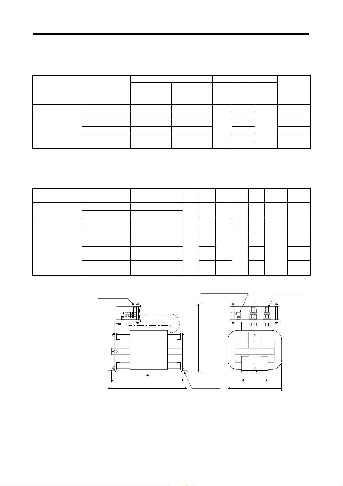
13.9.5 No-fuse breakers, fuses, magnetic contactors.
Always use one no-fuse breakers and one magnetic contactor with one drive unit.
Converter unit Drive unit
No-fuse breaker Fuse
Magnetic
contactor
Power factor
improving DC
reactor is not used
Power factor
improving DC
reactor is used
Class
Current
[A]
Voltage
AC [V]
MR-J3-CR55K
MR-J3-DU30KB 400A frame 250A 225A frame 225A 450
250
S-N150
MR-J3-DU37KB 400A frame 300A 400A frame 300A 500 S-N180
MR-J3-DU30KB4 225A frame 150A 225A frame 125A
T
225
600
S-N95
MR-J3-CR55K4
MR-J3-DU37KB4 225A frame 175A 225A frame 150A 250 S-N125
MR-J3-DU45KB4 225A frame 225A 225A frame 175A 350 S-N150
MR-J3-DU55KB4 400A frame 250A 225A frame 225A 400 S-N180
13.9.6 Power factor improving DC reactor
The input power factor is improved to about 95%.
[Unit: mm]
Converter unit Drive unit
Power factor improving
DC reactor
W D H W1 X
Terminal
screw
Mass
[kg (lb)]
MR-J3-CR55K
MR-J3-DU30KB MR-DCL30K
135
255 215 80 232 M12
9.5
(20.94)
MR-J3-DU37KB MR-DCL37K
MR-J3-DU30KB4 MR-DCL30K-4 205
200
75 175
M8
6.5
(14.33)
MR-J3-CR55K4
MR-J3-DU37KB4 MR-DCL37K-4 225
80
197
7
(15.43)
MR-J3-DU45KB4 MR-DCL45K-4 240 212
7.5
(16.54)
MR-J3-DU55KB4 MR-DCL55K-4 260 215 232
9.5
(20.94)
H or less
X
D or less
Terminal cover
Terminal screw
Terminal block (M3.5 screw)
For thermal sensor
P
1
P
2
Approx. W1
W or less
Mounting hole
for M8
1.5
1.5
13 - 85
13. SERVO AMPLIFIERS WITH A LARGE CAPACITY
(
30k TO 55kW
)
13.9.7 Line noise filter (FR-BLF)
POINT
This section explains how to use the line noise filter unique to servo amplifiers
with a large capacity. Other noise reduction products are the same as those
for servo amplifiers with 22kW or less. Refer to section 11.17.
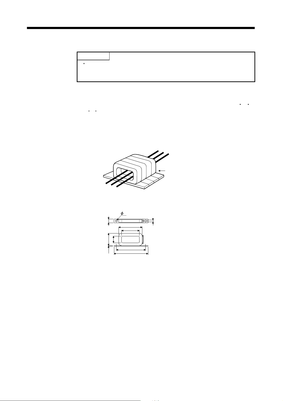
This filter is effective in suppressing noises radiated from the power supply side and output side of the
converter unit, drive unit and also in suppressing high-frequency leakage current (zero-phase current)
especially within 0.5MHz to 5MHz band. The filters are used with the converter power supply wires (L
1
L
2
L
3
)
and drive unit power wires (U
V W).
(1) Usage
Pass the 3-phase wires through four line noise filters. When using the line noise filters with the power wires,
passing the power wires together with the ground wire will reduce the filter effect. Run the ground wire
separately from the power wires.
Use four FR-BLFs.
(2) Outline drawing
[Unit: mm]
160
180
130
85
8
0
2
.
3
3
5
3
1
.
5
7
7