sh030051g.pdf - 第90页
3 - 35 3. SIGNALS AND WI RING 3.10 Connection of se rvo amplifier and servo motor CAUTION During power-on, do not open or clos e the motor powe r line. Otherwise, a malfunction or faulty may occur. 3.10.1 Connection inst…
3 - 34
3. SIGNALS AND WIRING
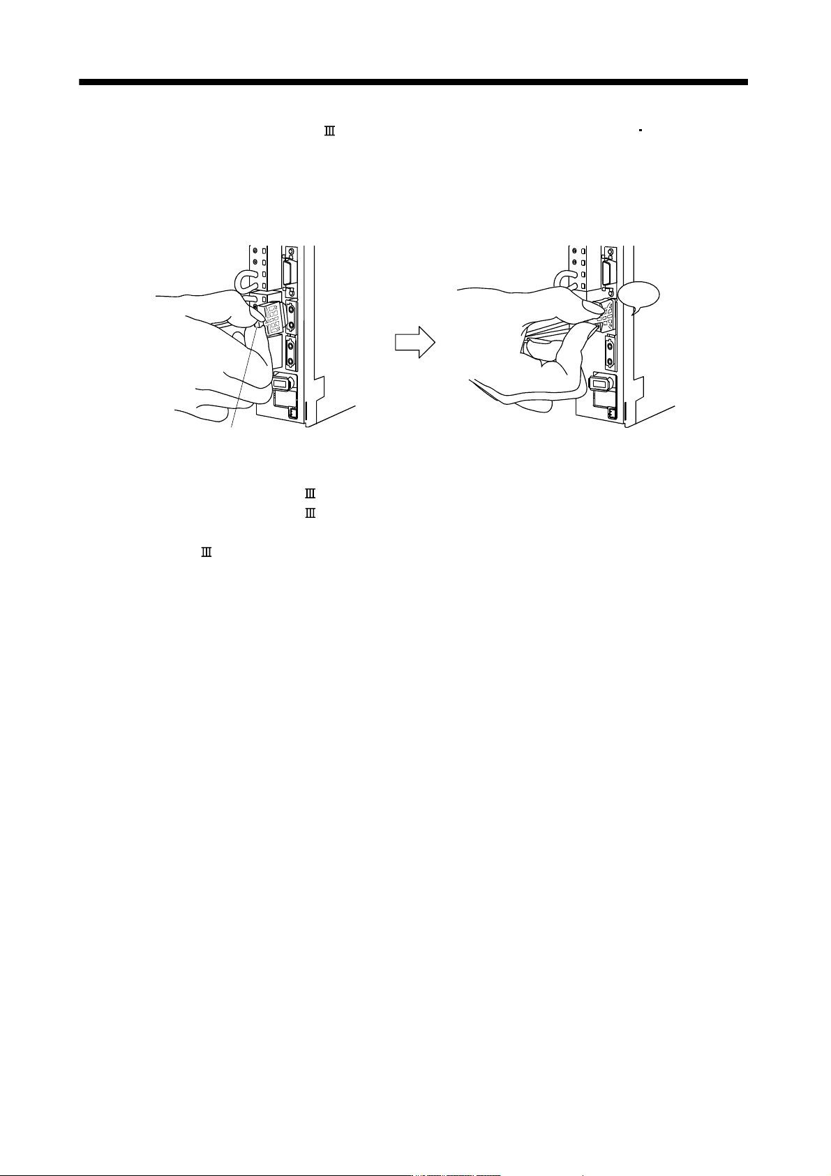
3) With holding a tab of SSCNET
cable connector, make sure to insert it into CN1A CN1B connector
of servo amplifier until you hear the click.
If the end face of optical code tip is dirty, optical transmission is interrupted and it may cause
malfunctions.
If it becomes dirty, wipe with a bonded textile, etc.
Do not use solvent such as alcohol.
Click
Tab
(b) Removal
With holding a tab of SSCNET
cable connector, pull out the connector.
When pulling out the SSCNET
cable from servo amplifier, be sure to put the cap on the connector
parts of servo amplifier to prevent it from becoming dirty.
For SSCNET
cable, attach the tube for protection optical code's end face on the end of connector.
3 - 35
3. SIGNALS AND WIRING
3.10 Connection of servo amplifier and servo motor
CAUTION
During power-on, do not open or close the motor power line. Otherwise, a
malfunction or faulty may occur.
3.10.1 Connection instructions
WARNING
Insulate the connections of the power supply terminals to prevent an electric
shock.
CAUTION
Connect the wires to the correct phase terminals (U, V, W) of the servo amplifier
and servo motor. Not doing so may cause unexpected operation.
Do not connect AC power supply directly to the servo motor. Otherwise, a fault
may occur.
POINT
Refer to section 11.1 for the selection of the encoder cable.
This section indicates the connection of the servo motor power (U, V, W). Use of the optional cable and
connector set is recommended for connection between the servo amplifier and servo motor. When the
options are not available, use the recommended products. Refer to section 11.1 for details of the options.
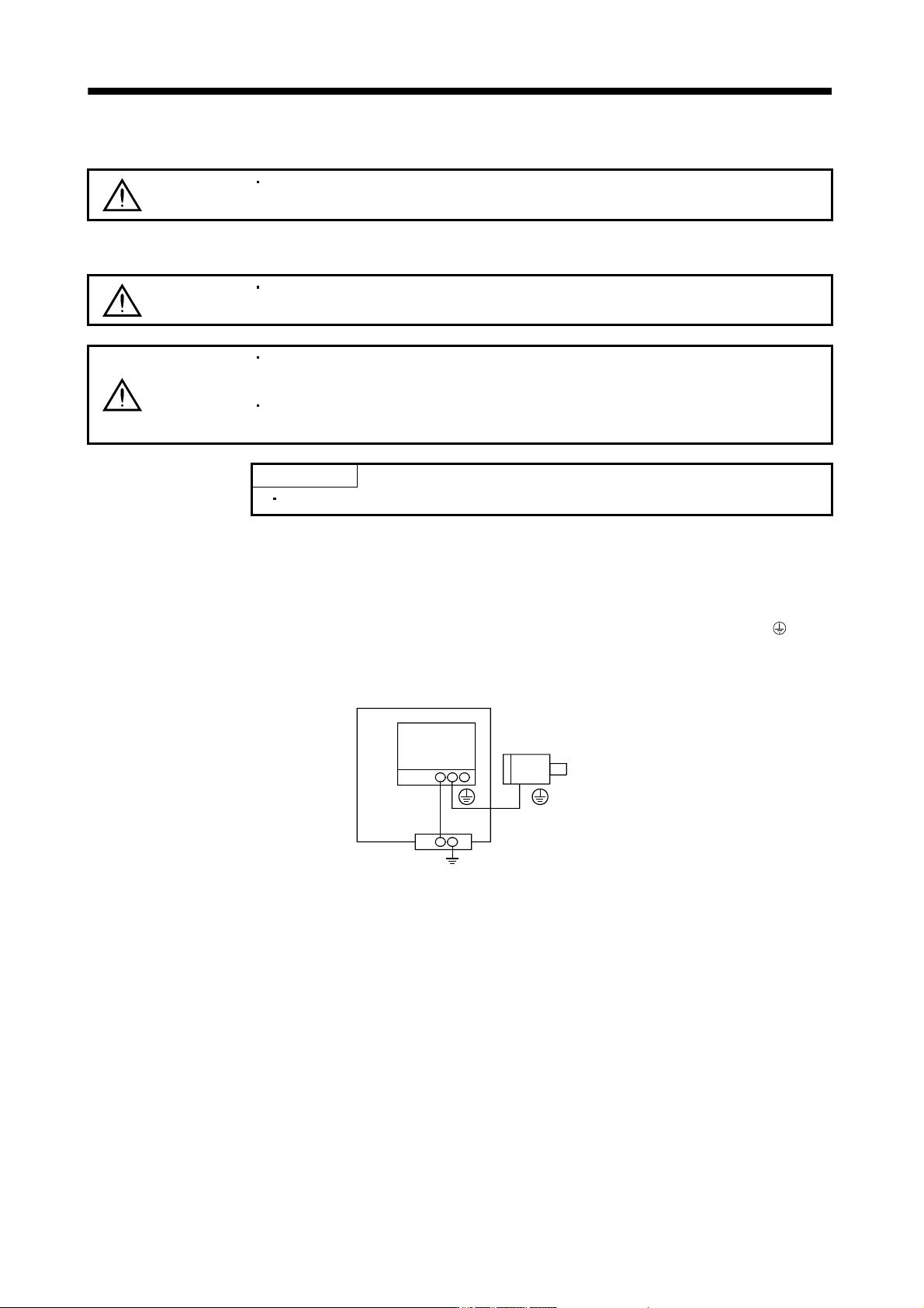
(1) For grounding, connect the earth cable of the servo motor to the protective earth (PE) terminal (
) of the
servo amplifier and connect the ground cable of the servo amplifier to the earth via the protective earth of
the control box. Do not connect them directly to the protective earth of the control panel.
Servo
amplifier
Servo motor
PE terminal
Control box
(2) Do not share the 24VDC interface power supply between the interface and electromagnetic brake. Always
use the power supply designed exclusively for the electromagnetic brake.
3 - 36
3. SIGNALS AND WIRING
3.10.2 Power supply cable wiring diagrams
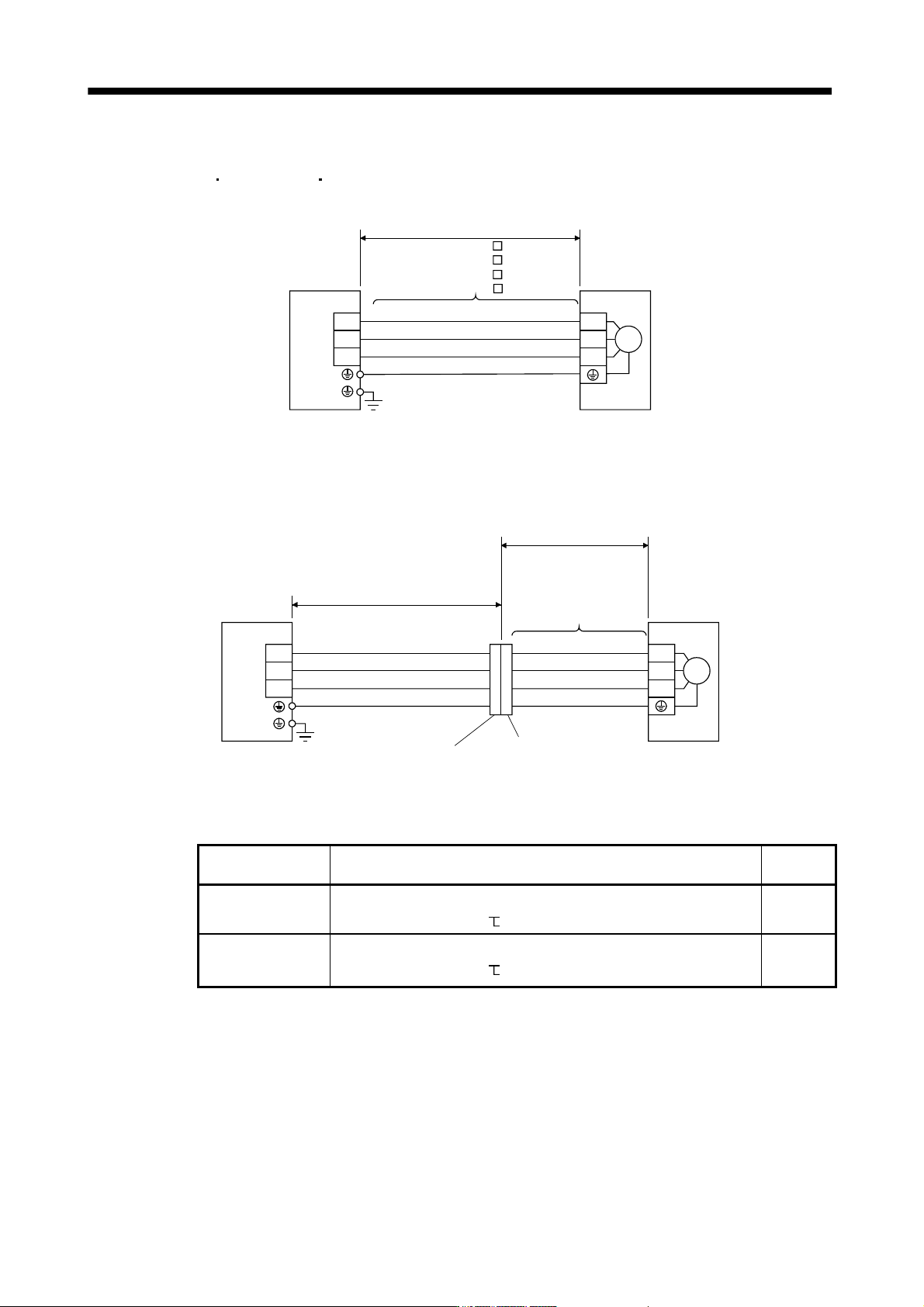
(1) HF-MP service
HF-KP series HF-KP series servo motor
(a) When cable length is 10m or less
CNP3
AWG 19(red)
AWG 19(white)
AWG 19(black)
AWG 19(green/yellow)
W
V
U
Servo motorServo amplifier
10m or less
MR-PWS1CBL M-A1-L
MR-PWS1CBL M-A2-L
MR-PWS1CBL M-A1-H
MR-PWS1CBL M-A2-H
M
U
V
W
(b) When cable length exceeds 10m
When the cable length exceeds 10m, fabricate an extension cable as shown below. In this case, the
motor power supply cable should be within 2m long.
Refer to section 11.11 for the wire used for the extension cable.
(Note)
Relay connector for
extension cable
a)
(Note)
Relay connector for motor
power supply cable
b)
MR-PWS1CBL2M-A1-L
MR-PWS1CBL2M-A2-L
MR-PWS1CBL2M-A1-H
MR-PWS1CBL2M-A2-H
MR-PWS2CBL03M-A1-L
MR-PWS2CBL03M-A2-L
CNP3
AWG 19(red)
AWG 19(white)
AWG 19(black)
U
V
W
Servo motorServo amplifier
Extension cable
50m or less
2m or less
U
V
W
M
AWG 19(green/yellow)
Note. Use of the following connectors is recommended when ingress protection (IP65) is necessary.
Relay connector Description
Protective
structure
a) Relay connector for
extension cable
Connector: RM15WTPZ-4P(71)
Cord clamp: RM15WTP-CP(5)(71)
(Hirose Electric)
Numeral changes depending on the cable OD.
IP65
b) Relay connector for
motor power supply
cable
Connector: RM15WTJA-4S(71)
Cord clamp: RM15WTP-CP(8)(71)
(Hirose Electric)
Numeral changes depending on the cable OD.
IP65