sh030051g.pdf - 第248页
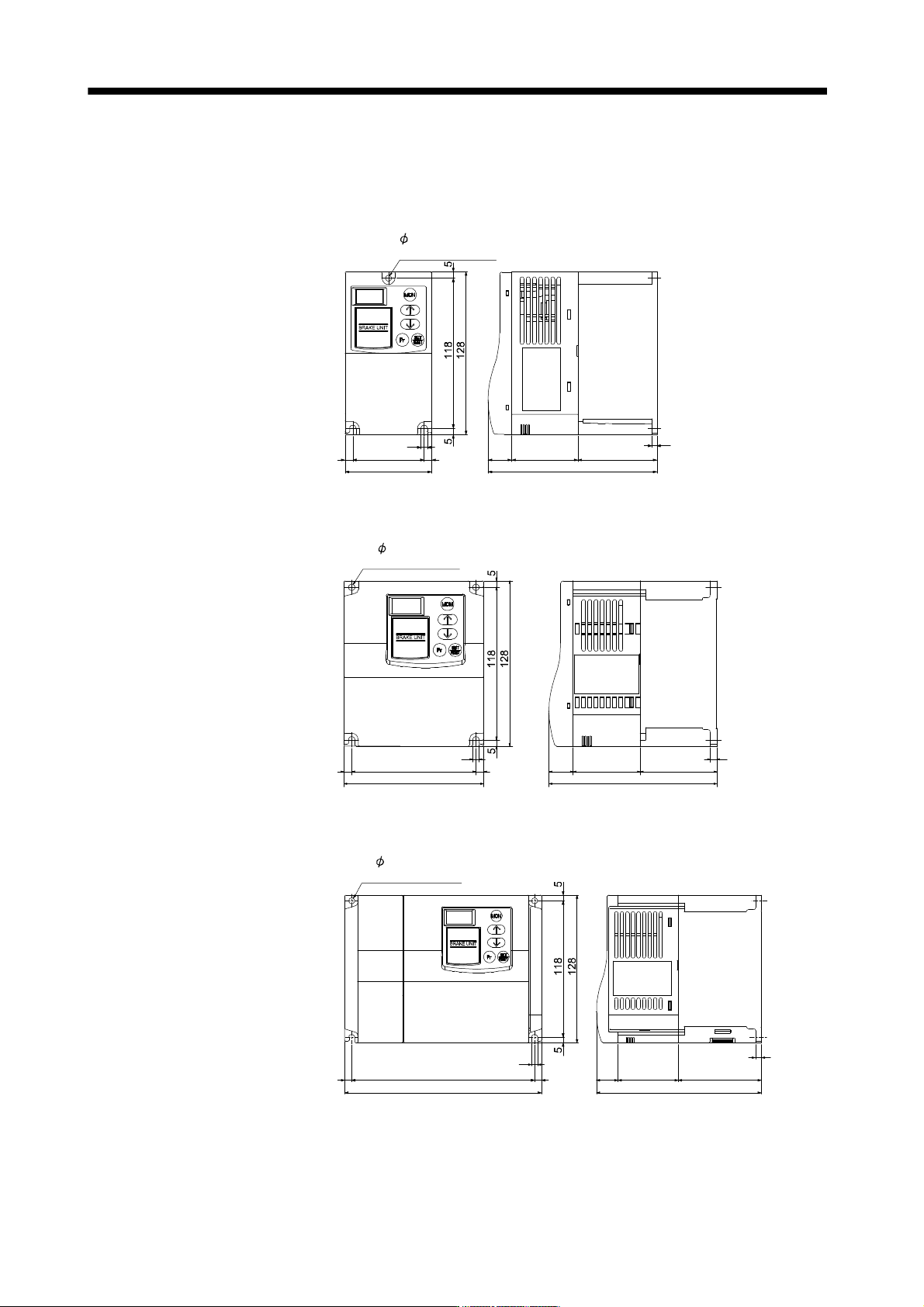
11 - 43 11. OPTIONS AND AUXILI ARY EQUIPMENT 11.3.4 Outline dimension drawings (1) FR-BU2- (H) brake unit [Unit: mm] FR-BU2-15K Rating plate 5 hole (Screw size: M4) 68 6 56 6 5 18.5 52 62 4 132.5 FR-BU2-30K FR-BU2-H30 K …
11 - 42
11. OPTIONS AND AUXILIARY EQUIPMENT
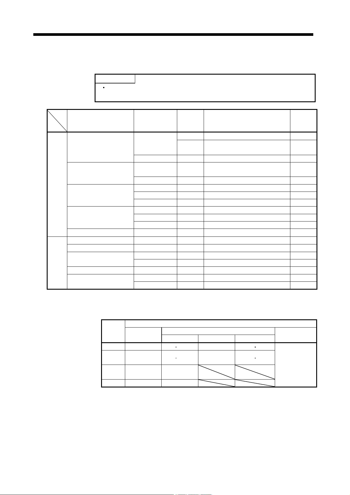
(5) Crimping terminals for P and N terminals of servo amplifier
(a) Recommended crimping terminals
POINT
Always use recommended crimping terminals or equivalent since some
crimping terminals cannot be installed depending on the size.
Servo amplifier Brake unit
Number of
connected
units
Crimping terminal (Manufacturer)
(Note 1)
Applicable
tool
200V MR-J3-500B FR-BU2-15K 1 FVD5.5-S4(Japan Solderless Terminal) c
class 2 8-4NS(Japan Solderless Terminal)
(Note 2)
d
FR-BU2-30K 1 FVD5.5-S4(Japan Solderless Terminal) c
MR-J3-700B FR-BU2-15K 2 8-4NS(Japan Solderless Terminal)
(Note 2)
d
FR-BU2-30K 1 FVD5.5-S4(Japan Solderless Terminal) c
MR-J3-11KB FR-BU2-15K 2 FVD8-6(Japan Solderless Terminal) a
FR-BU2-30K 1 FVD5.5-6(Japan Solderless Terminal) c
FR-BU2-55K 1 FVD14-6(Japan Solderless Terminal) b
MR-J3-15KB FR-BU2-15K 2 FVD8-6(Japan Solderless Terminal) a
FR-BU2-30K 1 FVD5.5-6(Japan Solderless Terminal) c
FR-BU2-55K 1 FVD14-6(Japan Solderless Terminal) b
MR-J3-22KB FR-BU2-55K 1 FVD14-8(Japan Solderless Terminal) b
400V MR-J3-500B4 FR-BU2-H30K 1 FVD5.5-S4(Japan Solderless Terminal) c
class MR-J3-700B4 FR-BU2-H30K 1 FVD5.5-S4(Japan Solderless Terminal) c
MR-J3-11KB4 FR-BU2-H30K 1 FVD5.5-6(Japan Solderless Terminal) c
FR-BU2-H55K 1 FVD5.5-6(Japan Solderless Terminal) c
MR-J3-15KB4 FR-BU2-H55K 1 FVD5.5-6(Japan Solderless Terminal) c
MR-J3-22KB4 FR-BU2-H55K 1 FVD5.5-8(Japan Solderless Terminal) c
FR-BU2-H75K 1 FVD14-8(Japan Solderless Terminal) b
Note 1. Symbols in the applicable tool field indicate applicable tools in (5)(b) of this section.
2. Coat the crimping part with an insulation tube.
(b) Applicable tool
Symbol
Servo amplifier side crimping terminals
Crimping
terminal
Applicable tool
Manufacturer
Body Head Dice
a FVD8-6 YF-1 E-4 YNE-38 DH-111 DH121
Japan Solderless
Terminal
b
FVD14-6
FVD14-8
YF-1 E-4 YNE-38 DH-112 DH122
c
FDV5.5-S4
FDV5.5-6
YNT-1210S
d 8-4NS YHT-8S
11 - 43
11. OPTIONS AND AUXILIARY EQUIPMENT
11.3.4 Outline dimension drawings
(1) FR-BU2- (H) brake unit
[Unit: mm]
FR-BU2-15K
Rating
plate
5 hole
(Screw size: M4)
68
6 56 6
5
18.5
52 62
4
132.5
FR-BU2-30K
FR-BU2-H30K
129.5
5
59
18.5
Rating
plate
52
2- 5 hole
(Screw size: M4)
5
108
6 6
96
FR-BU2-55K
FR-BU2-H55K, H75K
18.5
Rating
plate
52 72
5
142.5
5
61586
170
2- 5 hole
(Screw size: M4)
11 - 44
11. OPTIONS AND AUXILIARY EQUIPMENT
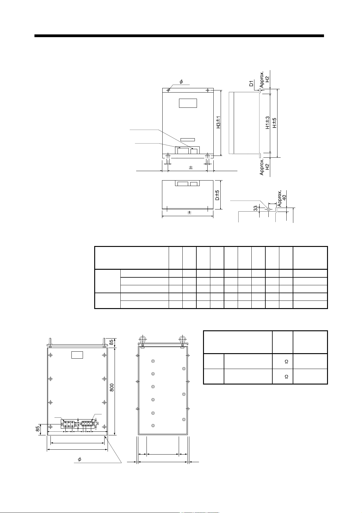
(2) FR-BR- (H) resistor unit
[Unit: mm]
2- C
Control circuit
terminal
Main circuit
terminal
W1 1
Approx. 35
Approx. 35
204
Hanging bolt
C
C
W 5
For FR-BR-55K/FR-BR-H55K, a hanging bolt
is placed on two locations (Indicated below).
(Note)
(Note)
Note. Ventilation ports are provided on both sides and the top. The bottom is open.
Resistor unit W W1 H H1 H2 H3 D D1 C
Approximate
mass
[kg]
200V
class
FR-BR-15K 170 100 450 410 20 432 220 3.2 6 15
FR-BR-30K 340 270 600 560 20 582 220 4 10 30
FR-BR-55K 480 410 700 620 40 670 450 3.2 12 70
400V
class
FR-BR-H30K 340 270 600 560 20 582 220 4 10 30
FR-BR-H55K 480 410 700 620 40 670 450 3.2 12 70
(3) MT-BR5- (H) resistor unit
[Unit: mm]
4 15 mounting hole
30075 75
4507.5 7.5
M6
M4
193
189
480
510
37 60 2110
NP
Resistor unit
Resistance
value
Approximate
mass
[kg]
200V
class
MT-BR5-55K 2.0
50
400V
class
MT-BR5-H75K 6.5
70