sh030051g.pdf - 第138页
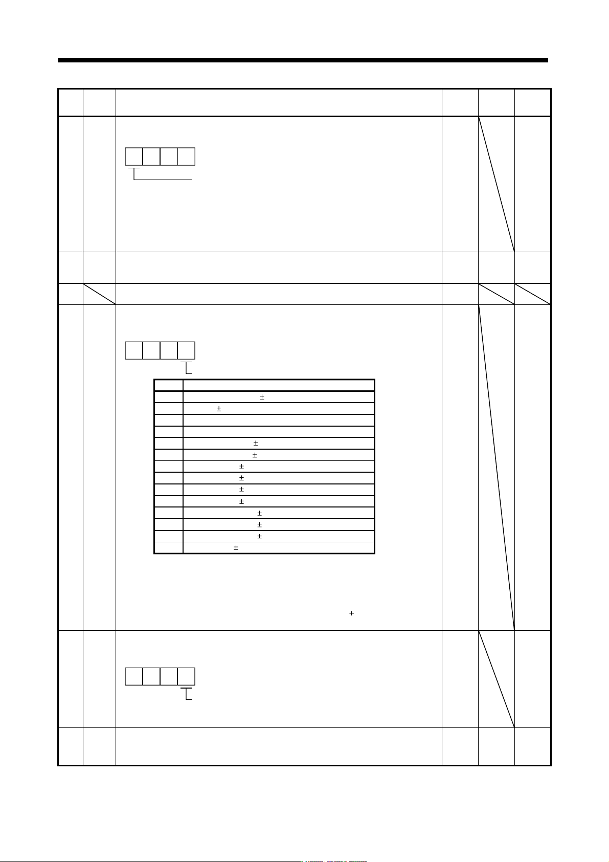
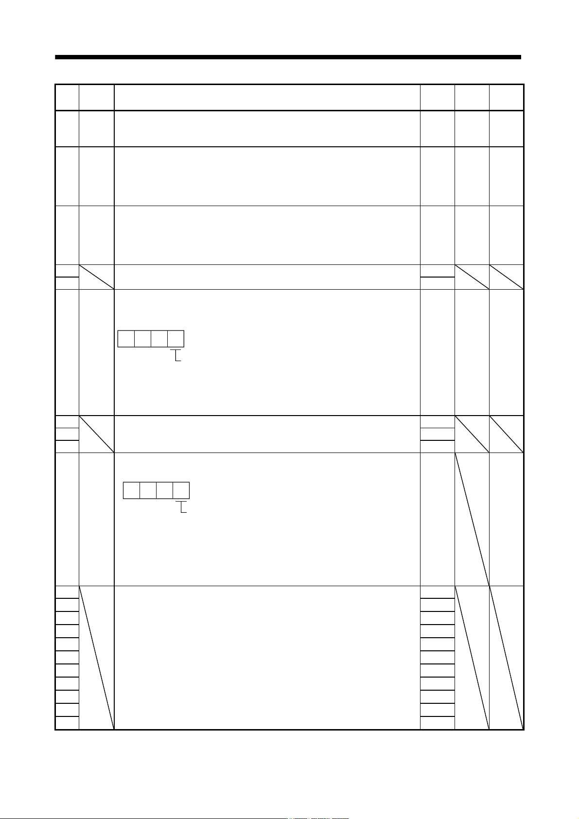
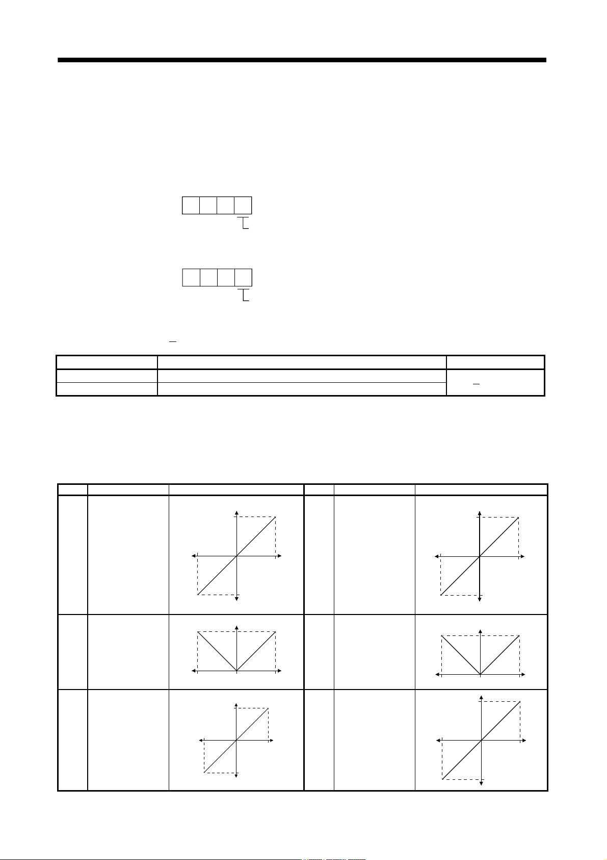
5 - 21 5. PARAMETERS No. Symbol Name and function Initial value Unit Setting range PC12 MO2 Analog monitor 2 offset Used to set the offset voltage of the analog monitor 2 (MO2) output. 0 mV -999 to 999 PC13 MOSDL Analog …
5 - 20
5. PARAMETERS
No. Symbol Name and function
Initial
value
Unit
Setting
range
PC06 *COP3
Function selection C-3
Select the error excessive alarm level setting for parameter No.PC01.
00
Error excessive alarm level setting selection
0: 1 [rev]unit
1: 0.1 [rev]unit
2: 0.01 [rev]unit
3: 0.001[rev]unit
0
This parameter is available to software version B1 or later.
0000h Refer to
Name
and
function
column.
PC07 ZSP Zero speed
Used to set the output range of the zero speed (ZSP).
Zero speed signal detection has hysteresis width of 20r/min (Refer to section 3.5 (2) (b))
50 r/min 0
to
10000
PC08 For manufacturer setting
Do not change this value by any means.
0
PC09 MOD1
Analog monitor 1 output
Used to selection the signal provided to the analog monitor 1 (MO1) output. (Refer to
section 5.3.3)
C
B
5
6
7
8
9
A
D
0
1
2
3
4
Analog monitor 1 (MO1) output selection
0
Setting
Feedback position ( 10V/100 Mpulses) (Note 1, 3)
Servo motor speed ( 8V/max. speed)
Torque ( 8V/max. torque) (Note 2)
Servo motor speed (+8V/max. speed)
Torque (+8V/max. torque) (Note 2)
Current command ( 8V/max. current command)
Speed command ( 8V/max. current command)
Droop pulses ( 10V/100 pulses) (Note 1)
Droop pulses ( 10V/1000 pulses) (Note 1)
Droop pulses ( 10V/10000 pulses) (Note 1)
Droop pulses ( 10V/100000 pulses) (Note 1)
Feedback position ( 10V/1 Mpulses) (Note 1, 3)
Feedback position ( 10V/10 Mpulses) (Note 1, 3)
Bus voltage ( 8V/400V)(Note 4)
Item
00
Note 1. Encoder pulse unit.
2. 8V is outputted at the maximum torque.
3. It can be used by the absolute position detection system.
4. For 400V class servo amplifier, the bus voltage becomes
8V/800V.
0000h Refer to
Name
and
function
column.
PC10 MOD2
Analog monitor 2 output
Used to selection the signal provided to the analog monitor 2 (MO2) output. (Refer to
section 5.3.3)
Select the analog monitor 2 (MO2) output
The settings are the same as those of parameter No.PC09.
000
0001h Refer to
Name
and
function
column.
PC11 MO1 Analog monitor 1 offset
Used to set the offset voltage of the analog monitor 1 (MO1) output.
0 mV -999
to
999
5 - 21
5. PARAMETERS
No. Symbol Name and function
Initial
value
Unit
Setting
range
PC12 MO2 Analog monitor 2 offset
Used to set the offset voltage of the analog monitor 2 (MO2) output.
0 mV -999
to
999
PC13 MOSDL Analog monitor feedback position output standard data Low
Used to set the standard position of feedback output with analog monitor 1 (M01) or 2
(M02).
For this parameter, the lower-order four digits of standard position in decimal numbers
are set.
0 pulse -9999
to
9999
PC14 MOSDH Analog monitor feedback position output standard data High
Used to set the standard position of feedback output with analog monitor 1 (M01) or 2
(M02).
For this parameter, the higher-order four digits of standard position in decimal numbers
are set.
0 10000
pulse
-9999
to
9999
PC15 For manufacturer setting
Do not change this value by any means.
0
PC16 0000h
PC17 **COP4 Function Selection C-4
Home position setting condition in the absolute position detection system can be
selected.
Selection of home position setting condition
0: Need to pass motor Z-phase after the power
supply is switched on.
1: Not need to pass motor Z-phase after the power
supply is switched on.
000
0000h Refer to
Name
and
function
column.
PC18 For manufacturer setting
Do not change this value by any means.
0000h
PC19 0000h
PC20 0000h
PC21 *BPS Alarm history clear
Used to clear the alarm history.
Alarm history clear
0: Invalid
1: Valid
When alarm history clear is made valid, the alarm
history is cleared at next power-on.
After the alarm history is cleared, the setting is
automatically made invalid (reset to 0).
000
0000h Refer to
Name
and
function
column.
PC22
For manufacturer setting
Do not change this value by any means.
0000h
PC23 0000h
PC24 0000h
PC25 0000h
PC26 0000h
PC27 0000h
PC28 0000h
PC29 0000h
PC30 0000h
PC31 0000h
PC32 0000h
5 - 22
5. PARAMETERS
5.3.3 Analog monitor
The servo status can be output to two channels in terms of voltage. The servo status can be monitored using
an ammeter.
(1) Setting
Change the following digits of parameter No.PC09, PC10.
Analog monitor (MO1) output selection
(Signal output to across MO1-LG)
Analog monitor (MO2) output selection
(Signal output to across MO2-LG)
000
000
Parameter No.PC09
Parameter No.PC10
Parameters No.PC11 and PC12 can be used to set the offset voltages to the analog output voltages. The
setting range is between
999 and 999mV.
Parameter No. Description Setting range [mV]
PC11 Used to set the offset voltage for the analog monitor 1 (MO1).
999 to 999
PC12 Used to set the offset voltage for the analog monitor 2 (MO2).
(2) Set content
The servo amplifier is factory-set to output the servo motor speed to analog monitor 1 (MO1) and the torque
to analog monitor (MO2). The setting can be changed as listed below by changing the parameter No.PC14
and PC12 value.
Refer to (3) for the measurement point.
Setting Output item Description Setting Output item Description
0 Servo motor speed
Max. speed
CW direction
CCW direction
Max. speed
0
8[V]
-8[V]
1 Torque (Note 3)
Max. torque
Driving in CW
direction
Driving in CCW
direction
Max. torque
0
8[V]
-8[V]
2 Servo motor speed
CCW direction
Max. speed Max. speed0
8[V]
CW direction
3 Torque (Note 3)
Driving in CCW
direction
Max. torque
Max. torque0
8[V]
Driving in CW
direction
4 Current command
Max. current command
(Max. torque command)
C
W
d
ir
ec
ti
o
n
CCW direction
Max. current command
(Max. torque command)
0
8[V]
-8[V]
5 Speed command
Max. speed
CW direction
CCW direction
Max. speed
0
8[V]
-8[V]