sh030051g.pdf - 第261页
11 - 56 11. OPTIONS AND AUXILI ARY EQUIPMENT 11.6 External dynamic brake POINT Configure up a sequence which switches off the contact of the brake unit after (or as soon as) it has turned off the serv o on signal at a po…
11 - 55
11. OPTIONS AND AUXILIARY EQUIPMENT
(6) Specifications
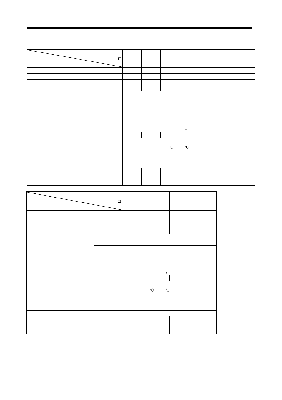
Power regeneration common converter
FR-CV-
Item
7.5K 11K 15K 22K 30K 37K 55K
Total of connectable servo amplifier capacities [kW] 3.75 5.5 7.5 11 15 18.5 27.5
Maximum servo amplifier capacity [kW] 3.5 5 7 11 15 15 22
Output
Total of connectable servo motor
rated currents [A]
33 46 61 90 115 145 215
Regenerative
braking torque
Short-time
rating
Total capacity of applicable servo motors, 300% torque, 60s (Note 1)
Continuous
rating
100% torque
Power supply
Rated input AC voltage/frequency Three-phase 200 to 220V 50Hz, 200 to 230V 60Hz
Permissible AC voltage fluctuation Three-phase 170 to 242V 50Hz, 170 to 253V 60Hz
Permissible frequency fluctuation 5%
Power supply capacity (Note 2) [kVA] 17 20 28 41 52 66 100
Protective structure (JEM 1030), cooling system Open type (IP00), forced cooling
Environment
Ambient temperature -10
to +50 (non-freezing)
Ambient humidity 90%RH or less (non-condensing)
Ambience Indoors (without corrosive gas, flammable gas, oil mist, dust and dirt)
Altitude, vibration 1000m or less above sea level, 5.9m/s
2
2 or less
No-fuse breaker or leakage current breaker
30AF
30A
50AF
50A
100AF
75A
100AF
100A
225AF
125A
225AF
125A
225AF
175A
Magnetic contactor S-N20 S-N35 S-N50 S-N65 S-N95 S-N95 S-N125
Power regeneration common converter
FR-CV-H
Item
22K 30K 37K 55K
Total of connectable servo amplifier capacities [kW] 11 15 18.5 27.5
Maximum servo amplifier capacity [kW] 11 15 15 22
Output
Total of connectable servo motor
rated currents [A]
43 57 71 110
Regenerative
braking torque
Short-time
rating
Total capacity of applicable servo motors, 300%
torque, 60s (Note 1)
Continuous
rating
100% torque
Power supply
Rated input AC voltage/frequency Three-phase 380 to 480V, 50Hz/60Hz
Permissible AC voltage fluctuation Three-phase 323 to 528V, 50Hz/60Hz
Permissible frequency fluctuation 5%
Power supply capacity [kVA] 41 52 66 100
Protective structure (JEM 1030), cooling system Open type (IP00), forced cooling
Environment
Ambient temperature -10
to +50 (non-freezing)
Ambient humidity 90%RH or less (non-condensing)
Ambience
Indoors (without corrosive gas, flammable gas, oil
mist, dust and dirt)
Altitude, vibration 1000m or less above sea level, 5.9m/s
2
2 or less
No-fuse breaker or leakage current breaker
60AF
60A
100AF
175A
100AF
175A
225AF
125A
Magnetic contactor S-N25 S-N35 S-N35 S-N65
Note 1. This is the time when the protective function of the FR-CV-(H) is activated. The protective function of the servo amplifier is
activated in the time indicated in section 10.1.
2. When connecting the capacity of connectable servo amplifier, specify the value of servo amplifier.
11 - 56
11. OPTIONS AND AUXILIARY EQUIPMENT
11.6 External dynamic brake
POINT
Configure up a sequence which switches off the contact of the brake unit after
(or as soon as) it has turned off the servo on signal at a power failure or
failure.
For the braking time taken when the dynamic brake is operated, refer to
section 10.3.
The brake unit is rated for a short duration. Do not use it for high duty.
When using the 400V class dynamic brake, the power supply voltage is
restricted to 1-phase 380VAC to 463VAC (50Hz/60Hz).
(1) Selection of dynamic brake
The dynamic brake is designed to bring the servo motor to a sudden stop when a power failure occurs
or the protective circuit is activated, and is built in the 7kW or less servo amplifier. Since it is not built
in the 11kW or more servo amplifier, purchase it separately if required. Assign the dynamic brake interlock
(DB) to any of CN3-9, CN3-13, and CN3-15 pins in parameter No.PD07 to PD09.
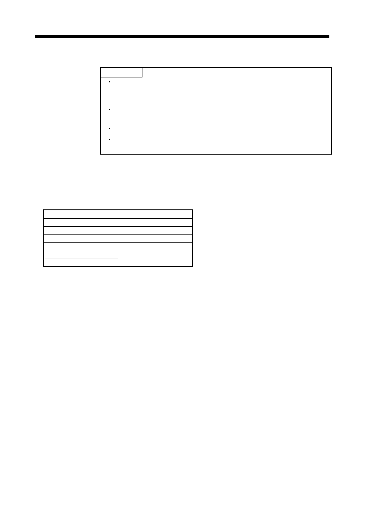
Servo amplifier Dynamic brake
MR-J3-11KB DBU-11K
MR-J3-15KB DBU-15K
MR-J3-22KB DBU-22K
MR-J3-11KB4 DBU-11K-4
MR-J3-15KB4
DBU-22K-4
MR-J3-22KB4
11 - 57
11. OPTIONS AND AUXILIARY EQUIPMENT
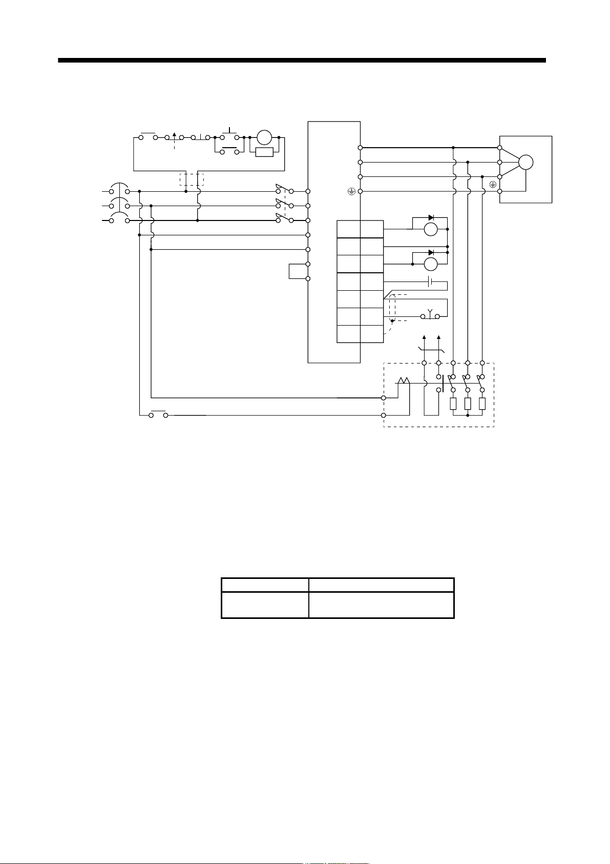
(2) Connection example
NFB
L11
L21
U
V
W
U
V
W
M
Servo amplifier
Servo motor
RA2
MC
SK
MC
ON
OFF
ALM
RA1
Operation-ready
EM1
L
3
L2
L
1
(Note 5)
Power
supply
13 U14 V W
External dynamic brake
a
b
(Note 1)
P
P
1
(Note 2)
(Note 4)
EM1
3
20
SDPlate
DICOM
10
DB
(Note 3)
DOCOM
5
DICOM
ALM15
CN3
RA1
RA2
MC
(Note 6)
Note 1. Terminals 13, 14 are normally open contact outputs. If the dynamic brake is seized, terminals 13, 14 will open.
Therefore, configure up an external sequence to prevent servo-on.
2. For the servo amplifiers from 11k to 22kW, be sure to connect P
1 and P. (Factory-wired)
When using the power factor DC reactor, refer to section 11.13.
3. Assign the dynamic brake interlock (DB) in the parameters No.PD07 to PD09.
4. Stepdown transformer is required for coil voltage of magnetic contactor more than 200V class in 400V class servo amplifiers.
5. Refer to section 1.3 for the power supply specification.
6. The power supply voltage of the inside magnet contactor for 400V class dynamic brake DBU-11K-4 and DBU-22K-4 is restricted
as follows. When using these dynamic brakes, use them within the range of the power supply.
Dynamic brake Power supply voltage
DBU-11K-4
DBU-22K-4
1-phase 380 to 463VAC 50Hz/60Hz