sh030051g.pdf - 第367页
13 - 66 13. SERVO AMPLIFIERS WI TH A LARGE CAPACITY ( 30k TO 55kW ) (2) MR-J3-DU30KB4 MR-J3-DU37KB4 [Unit: mm] 240 Approx. 200 Approx. 200 328 128 180 120 60 6 219.2 TE2 TE3 TE1 For mounting MR-J3BAT Approx. 60 Approx. 8…
13 - 65
13. SERVO AMPLIFIERS WITH A LARGE CAPACITY
(
30k TO 55kW
)
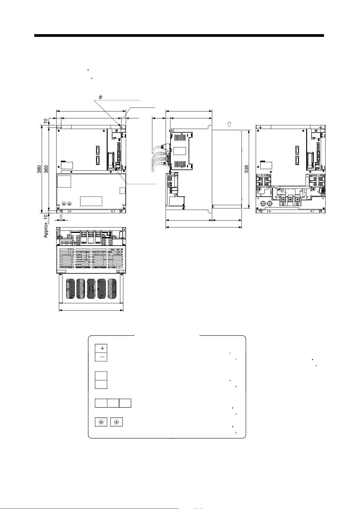
13.7.2 Drive unit
(1) MR-J3-DU30KB
MR-J3-DU37KB
MR-J3-DU45KB4
MR-J3-DU55KB4
[Unit: mm]
For mounting
MR-J3BAT
TE2-1
PE
TE2-1
20
260
Approx. 200
300
180
7
TE3
TE1
328
Approx. 200 128
277
TE1
TE3
Approx. 20
Approx. 80
2- 7 Installation hole
Cooling fan
wind direction
Terminal block layout
(Terminal cover removed)
Mass: 26[kg] (57.3[lb])
TE1
TE2-1
TE3
L11
L
21
PE
Terminal block signal layout
Terminal block screw: M6
Tightening torque: 3.0 [N m]
(26.6 [lb in])
L
L
Terminal block screw: M4
Tightening torque: 1.2 [N m]
(10.6 [lb in])
Terminal block screw: M10
Tightening torque: 10.0 [N m]
(88.5 [lb in])
Terminal block screw: M10
Tightening torque: 10.0 [N m]
(88.5 [lb in])
Mounting screw
Screw size: M6
Tightening torque: 5.4 [N m]
(47.8 [lb in])
UVW
13 - 66
13. SERVO AMPLIFIERS WITH A LARGE CAPACITY
(
30k TO 55kW
)
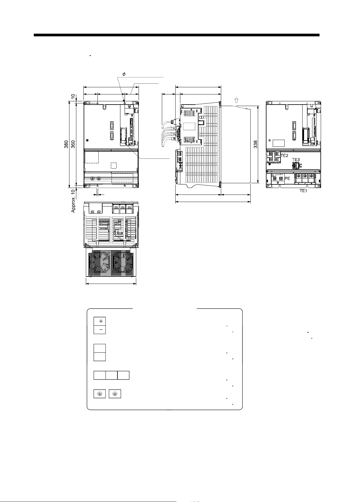
(2) MR-J3-DU30KB4
MR-J3-DU37KB4
[Unit: mm]
240
Approx. 200
Approx. 200
328
128
180
12060
6
219.2
TE2
TE3
TE1
For mounting
MR-J3BAT
Approx. 60
Approx. 80
2- 6 Installation hole
Cooling fan
wind direction
Terminal block layout
(Terminal cover removed)
Mass: 18[kg] (39.7[lb])
TE1
TE2
TE3
L11
L
21
PE
Terminal block signal layout
Terminal block screw: M6
Tightening torque: 3.0 [N m]
(26.6 [lb in])
L
L
Terminal block screw: M4
Tightening torque: 1.2 [N m]
(10.6 [lb in])
Terminal block screw: M8
Tightening torque: 6.0 [N m]
(53.1 [lb in])
Terminal block screw: M8
Tightening torque: 6.0 [N m]
(53.1 [lb in])
Mounting screw
Screw size: M5
Tightening torque: 3.2 [N m]
(28.3 [lb in])
UVW
13 - 67
13. SERVO AMPLIFIERS WITH A LARGE CAPACITY
(
30k TO 55kW
)
13.8 Characteristics
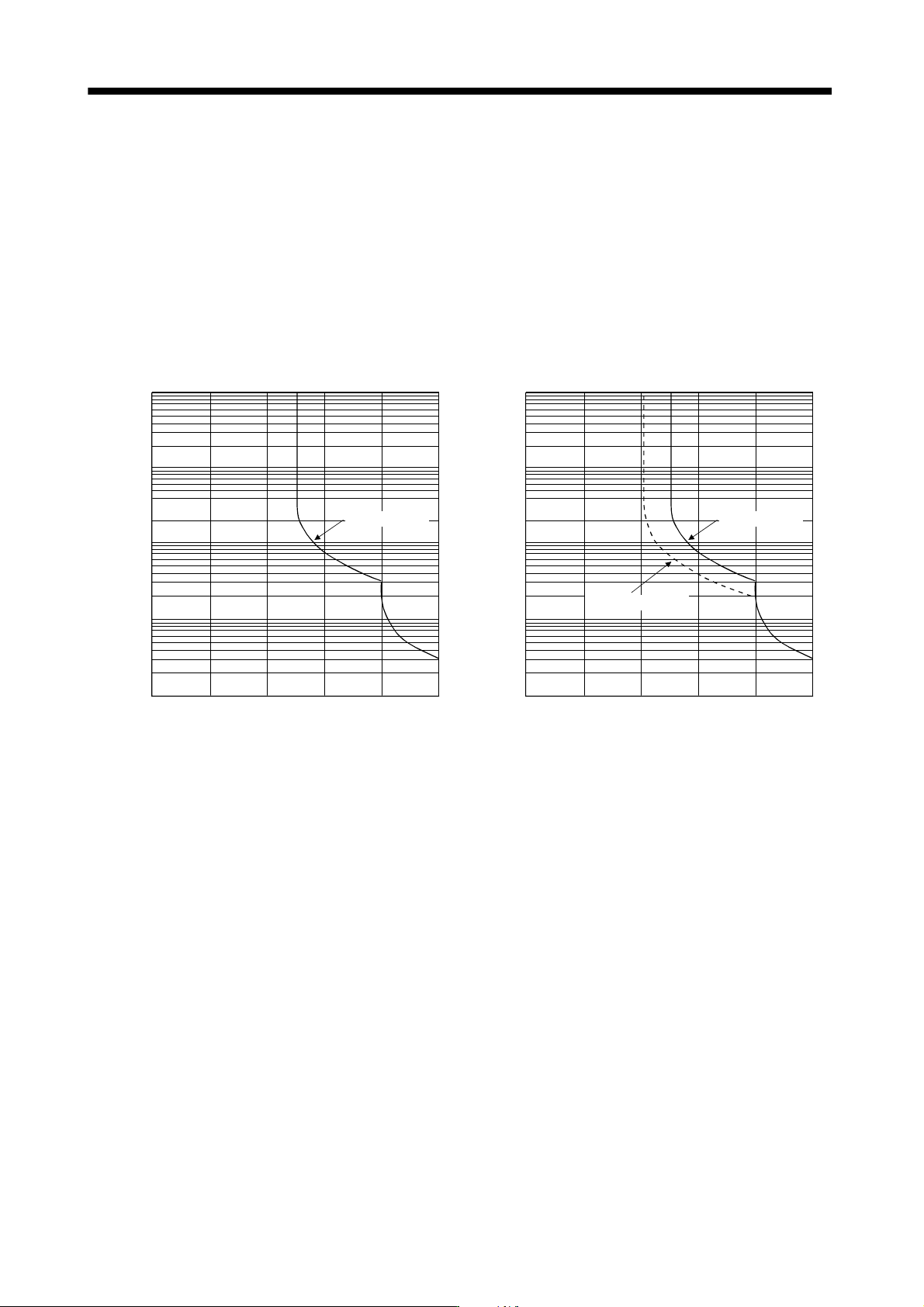
13.8.1 Overload protection characteristics
An electronic thermal relay is built in the converter unit and drive unit to protect the servo motor, converter unit
and drive unit from overloads.
Overload 1 alarm (50) occurs if overload operation performed is above the electronic thermal relay protection
curve shown below. Overload 2 alarm (51) occurs if the maximum current flew continuously for several
seconds due to machine collision, etc. Use the equipment on the left-hand side area of the continuous or
broken line in the graph.
It is recommended to use the machine which generates unbalanced torque, e.g. a vertical lift application, so
that the unbalanced torque is not more than 70% of the rated torque.
10000
1000
100
10
1
0 100 200 250
During rotation
(Note 2)
Operation time [s]
Load ratio [%]
Converter unit
10000
1000
100
10
1
0 100 200 250
During servo lock
During rotation
(Note 2)
Operation time [s]
(Note 1) Load ratio [%]
Drive unit
Note 1. If operation that generates torque more than 100% of the rating is performed with an abnormally high frequency in a servo motor
stop status (servo lock status) or in a 30r/min or less low-speed operation status, the drive unit may fail even when the electronic
thermal relay protection is not activated.
2. Load ratio 100% indicates the rated output of each converter unit and drive unit. Refer to section 13.1.4 for rated output.
Fig. 13.1 Overload protection characteristics