sh030051g.pdf - 第92页
3 - 37 3. SIGNALS AND WI RING (2) HF-SP series HC-RP series HC-UP series HC-LP series servo motor POINT Insert a contact in the direction shown in the figure. If inse rted in the wrong direction, the contact is damaged a…
3 - 36
3. SIGNALS AND WIRING
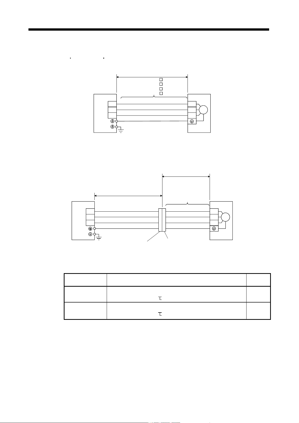
3.10.2 Power supply cable wiring diagrams
(1) HF-MP service
HF-KP series HF-KP series servo motor
(a) When cable length is 10m or less
CNP3
AWG 19(red)
AWG 19(white)
AWG 19(black)
AWG 19(green/yellow)
W
V
U
Servo motorServo amplifier
10m or less
MR-PWS1CBL M-A1-L
MR-PWS1CBL M-A2-L
MR-PWS1CBL M-A1-H
MR-PWS1CBL M-A2-H
M
U
V
W
(b) When cable length exceeds 10m
When the cable length exceeds 10m, fabricate an extension cable as shown below. In this case, the
motor power supply cable should be within 2m long.
Refer to section 11.11 for the wire used for the extension cable.
(Note)
Relay connector for
extension cable
a)
(Note)
Relay connector for motor
power supply cable
b)
MR-PWS1CBL2M-A1-L
MR-PWS1CBL2M-A2-L
MR-PWS1CBL2M-A1-H
MR-PWS1CBL2M-A2-H
MR-PWS2CBL03M-A1-L
MR-PWS2CBL03M-A2-L
CNP3
AWG 19(red)
AWG 19(white)
AWG 19(black)
U
V
W
Servo motorServo amplifier
Extension cable
50m or less
2m or less
U
V
W
M
AWG 19(green/yellow)
Note. Use of the following connectors is recommended when ingress protection (IP65) is necessary.
Relay connector Description
Protective
structure
a) Relay connector for
extension cable
Connector: RM15WTPZ-4P(71)
Cord clamp: RM15WTP-CP(5)(71)
(Hirose Electric)
Numeral changes depending on the cable OD.
IP65
b) Relay connector for
motor power supply
cable
Connector: RM15WTJA-4S(71)
Cord clamp: RM15WTP-CP(8)(71)
(Hirose Electric)
Numeral changes depending on the cable OD.
IP65
3 - 37
3. SIGNALS AND WIRING
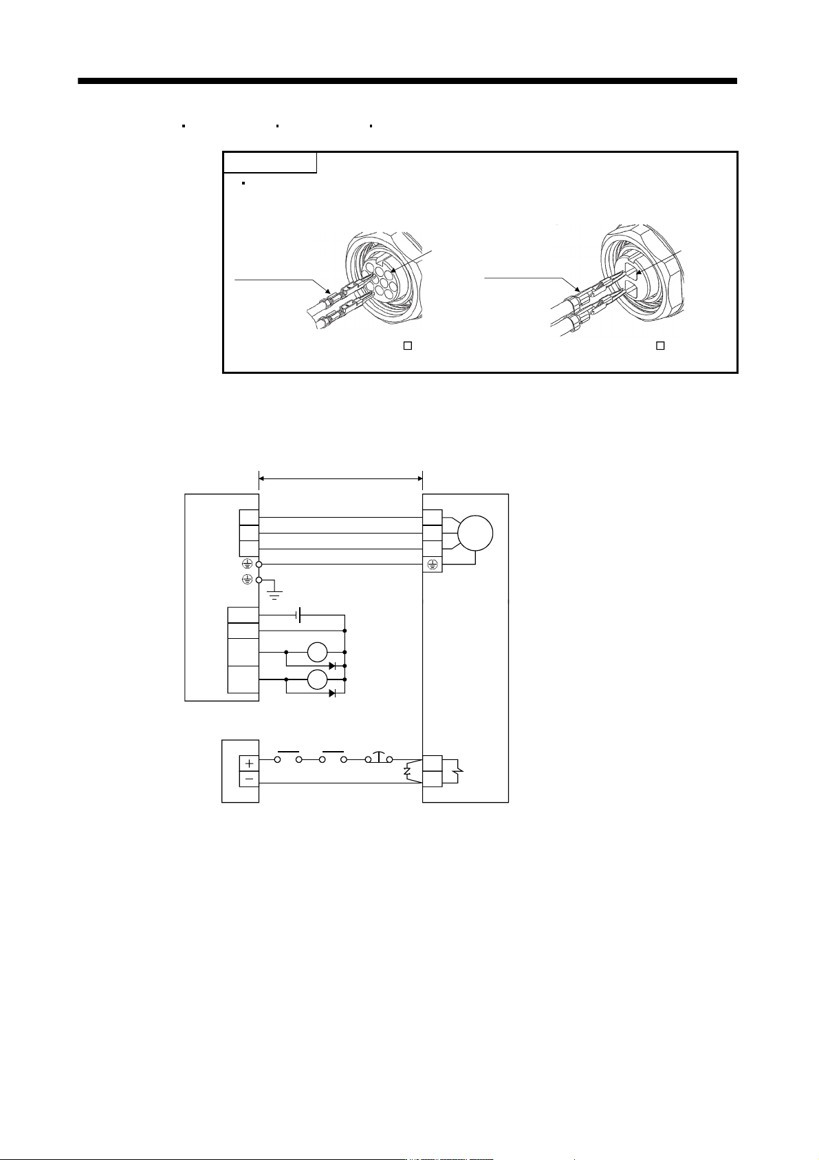
(2) HF-SP series
HC-RP series HC-UP series HC-LP series servo motor
POINT
Insert a contact in the direction shown in the figure. If inserted in the wrong
direction, the contact is damaged and falls off.
Soldered part
or crimping part
facing up
Soldered part or
crimping part
facing down
Pin No.1Pin No.1
For CM10-SP2S-For CM10-SP10S-
(a) Wiring diagrams
Refer to section 11.11 for the cables used for wiring.
1) When the power supply connector and the electromagnetic brake connector are separately supplied.
Servo motor
(Note)
Servo amplifier
M
U
V
W
B1
B2
U
V
W
24VDC power
supply for
electromagnetic
brake
50m or less
Forced
stop
(EM1)
Trouble
(ALM)
RA1
24VDC
ALM
DOCOM
DICOM
MBR
CN3
RA1
RA2
Electromagnetic
brake interlock
(MBR)
RA2
Note. There is no polarity in electromagnetic brake terminals B1 and B2.
3 - 38
3. SIGNALS AND WIRING
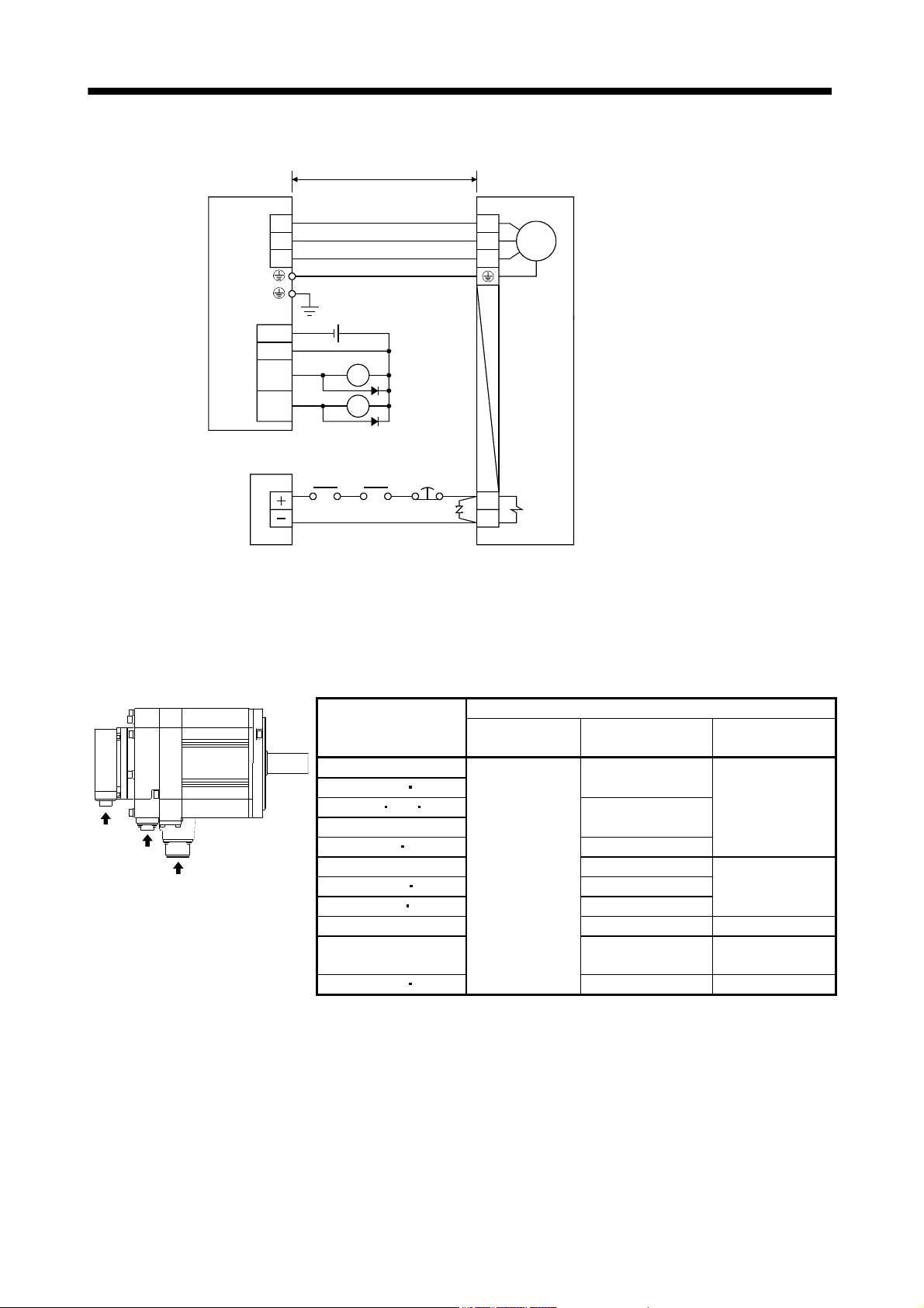
2) When the power supply connector and the electromagnetic brake connector are shared.
Servo motor
(Note)
Servo amplifier
M
U
V
W
B1
B2
U
V
W
24VDC power
supply for
electromagnetic
brake
50m or less
Forced
stop
(EM1)
Trouble
(ALM)
RA1
24VDC
ALM
DOCOM
DICOM
MBR
CN3
RA1
RA2
Electromagnetic
brake interlock
(MBR)
RA2
Note. There is no polarity in electromagnetic brake terminals B1 and B2.
(b) Connector and signal allotment
The connector fitting the servo motor is prepared as optional equipment. Refer to section 11.1. For types
other than those prepared as optional equipment, refer to chapter 3 in Servo Motor Instruction Manual,
Vol. 2 to select.
a
c
b
Servo motor
Servo motor side connectors
Encoder Power supply
Electromagnetic
brake
HF-SP52(4) to 152(4)
CM10-R10P
(DDK)
MS3102A18-10P
CM10-R2P
(DDK)
HF-SP51 81
HF-SP202 352 502(4)
MS3102A22-22P
HF-SP121 to 301
HF-SP421 702(4) CE05-2A32-17PD-B
HC-RP103 to 203 CE05-2A22-23PD-B
The connector for
power is shared
HC-RP353 503 CE05-2A24-10PD-B
HC-UP72 152 CE05-2A22-23PD-B
HC-UP202 to 502 CE05-2A24-10PD-B MS3102A10SL-4P
HC-LP52 to 152 CE05-2A22-23PD-B
The connector for
power is shared
HC-LP202 302 CE05-2A24-10PD-B MS3102A10SL-4P