sh030051g.pdf - 第372页
13 - 71 13. SERVO AMPLIFIERS WI TH A LARGE CAPACITY ( 30k TO 55kW ) 45 40 35 30 25 20 15 10 5 0 500 1000 1500 0 2000 HA-LP30K2 HA-LP37K2 Speed [r/min] Time constant [ms] 45 40 35 30 25 20 15 10 5 0 500 1000 1500 0 2000 H…
13 - 70
13. SERVO AMPLIFIERS WITH A LARGE CAPACITY
(
30k TO 55kW
)
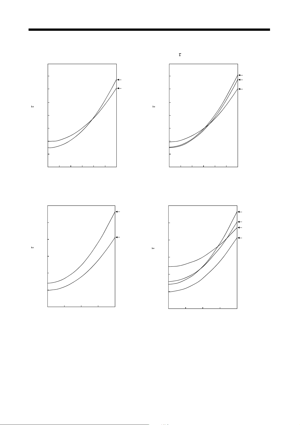
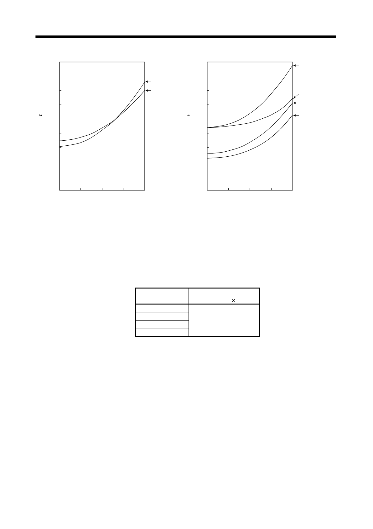
(b) Dynamic brake time constant
The following shows necessary dynamic brake time constant
for the equations (13.1).
40
35
30
25
20
15
10
5
0
200 600 100001200
Speed [r/min]
HA-LP30K1
HA-LP37K1
400 800
Time constant [ms]
40
35
30
25
20
15
10
5
0
200 600 100001200
Speed [r/min]
400 800
Time constant [ms]
HA-LP30K14
HA-LP37K14
HA-LP25K14
HA-LP1000r/min series
60
50
40
30
20
10
0
1000 150002000
HA-LP30K1M
500
HA-LP37K1M
Speed [r/min]
Time constant [ms]
60
50
40
30
20
10
0
1000 150002000
HA-LP30K1M4
500
HA-LP37K1M4
HA-LP45K1M4
HA-LP50K1M4
Speed [r/min]
Time constant [ms]
HA-LP1500r/min series
13 - 71
13. SERVO AMPLIFIERS WITH A LARGE CAPACITY
(
30k TO 55kW
)
45
40
35
30
25
20
15
10
5
0
500 1000 15000
2000
HA-LP30K2
HA-LP37K2
Speed [r/min]
Time constant [ms]
45
40
35
30
25
20
15
10
5
0
500 1000 15000
2000
HA-LP45K24
HA-LP55K24
HA-LP37K24
HA-LP30K24
Speed [r/min]
Time constant [ms]
HA-LP2000r/min series
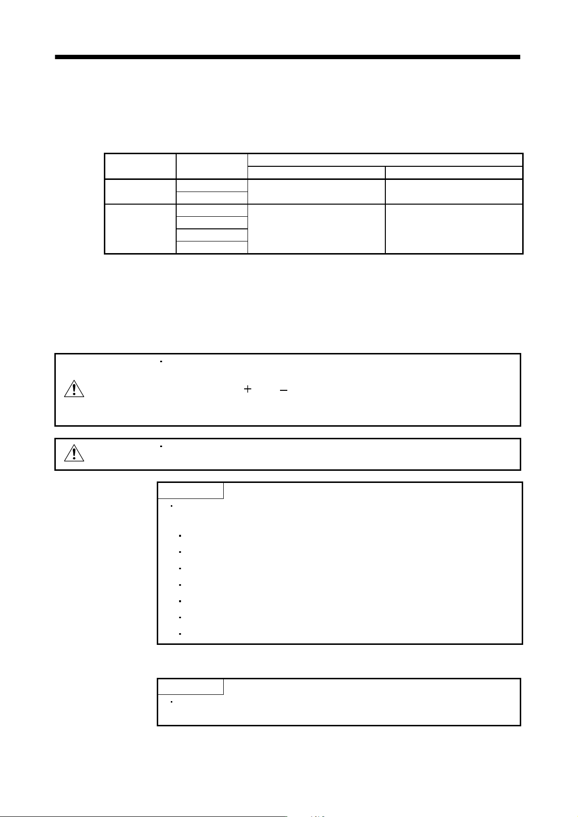
(2) The dynamic brake at the load inertia moment
Use the dynamic brake under the load inertia moment ratio indicated in the following table. If the load inertia
moment is higher than this value, the external dynamic brake may burn. If there is a possibility that the load
inertia moment may exceed the value, contact Mitsubishi.
The values of the load inertia moment ratio in the table are the values at the maximum rotation speed of the
servo motor.
Drive unit
Load inertia moment ratio
[Multiplier (
1)]
MR-J3-DU30KB(4)
MR-J3-DU37KB(4)
10
MR-J3-DU45KB4
MR-J3-DU55KB4
13 - 72
13. SERVO AMPLIFIERS WITH A LARGE CAPACITY
(
30k TO 55kW
)
13.8.4 Inrush currents at power-on of main circuit and control circuit
The following table indicates the inrush currents (reference data) that will flow when the maximum permissible
voltage (200V class: 253VAC, 400V class: 528VAC) is applied at the power supply capacity of 2500kVA and
the wiring length of 1m.
Converter unit Drive unit
Inrush currents (A
0-p)
Main circuit power supply (L
1
, L
2
, L
3
) Control circuit power supply (L
11
, L
21
)
MR-J3-CR55K
MR-J3-DU30KB
163A
(Attenuated to approx. 20A in 180ms)
18A
(Attenuated to approx. 0A in 100ms)
MR-J3-DU37KB
MR-J3-DU30KB4
339A
(Attenuated to approx. 20A in 70ms)
19A
(Attenuated to approx. 0A in 60ms)
MR-J3-CR55K4
MR-J3-DU37KB4
MR-J3-DU45KB4
MR-J3-DU55KB4
Since large inrush currents flow in the power supplies, always use no-fuse breakers and magnetic contactors.
(Refer to section 13.9.5.)
When circuit protectors are used, it is recommended to use the inertia delay type that will not be tripped by an
inrush current.
13.9 Options
WARNING
Before connecting any option or peripheral equipment, turn off the power and wait
for 20 minutes or more until the charge lamp turns off. Then, confirm that the
voltage between L
and L is safe with a voltage tester and others. Otherwise,
an electric shock may occur. In addition, always confirm from the front of the
converter unit whether the charge lamp is off or not.
CAUTION
Use the specified auxiliary equipment and options. Unspecified ones may lead to a
fault or fire.
POINT
Explanations on the following item are the same as those for servo amplifiers
with 22kW or less. Refer to the section below for details.
Cable/connector sets Refer to section 11.1.
Junction terminal block Refer to section 11.7.
MR Configurator Refer to section 11.8.
Battery Refer to section 11.9.
Relays Refer to section 11.15.
Surge absorbers Refer to section 11.16.
Radio noise filter (FR-BIF(-H)) Refer to section 11.17 (2) (e).
13.9.1 Cables and connectors
POINT
Other connectors are the same as those for servo amplifiers with 22kW or
less. Refer to section 11.1.