sh030051g.pdf - 第49页
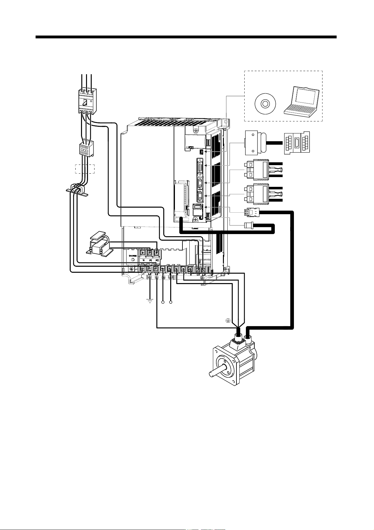
1 - 28 1. FUNCTIONS AND CONFIGURATIO N (7) MR-J3-11KB(4) to MR-J3-22KB(4) Line noise filter (FR-BLF) (Note 3) Power supply R S T Magne tic contactor (MC) No-fuse breaker (NFB) or fuse Regenerative option L 21 Servo ampli…
1 - 27
1. FUNCTIONS AND CONFIGURATION
(6) MR-J3-700B(4)
R S T
L
21
L
11
UVW
CP
L
1
L
2
L
3
CN5
CN3
CN2
CN1A
CN1B
CN4
P2
P1
Line noise filter
(FR-BLF)
(Note 3)
Power supply
Magnetic
contactor
(MC)
No-fuse breaker
(NFB) or fuse
(Note 2)
(Note 2)
Power factor
improving DC
reactor
(FR-BEL-(H))
Servo amplifier
Regenerative option
Servo motor
Junction
terminal
block
MR Configurator
Personal
computer
Servo system
controller or Front axis
servo amplifier CN1B
Rear servo amplifier
CN1A or Cap
(Note 1)
Battery
MR-J3BAT
Note 1. The battery (option) is used for the absolute position detection system in the position control mode.
2. The AC reactor can also be used. In this case, the DC reactor cannot be used. When not using DC reactor, short P
1 and P2.
3. Refer to section 1.3 for the power supply specification.
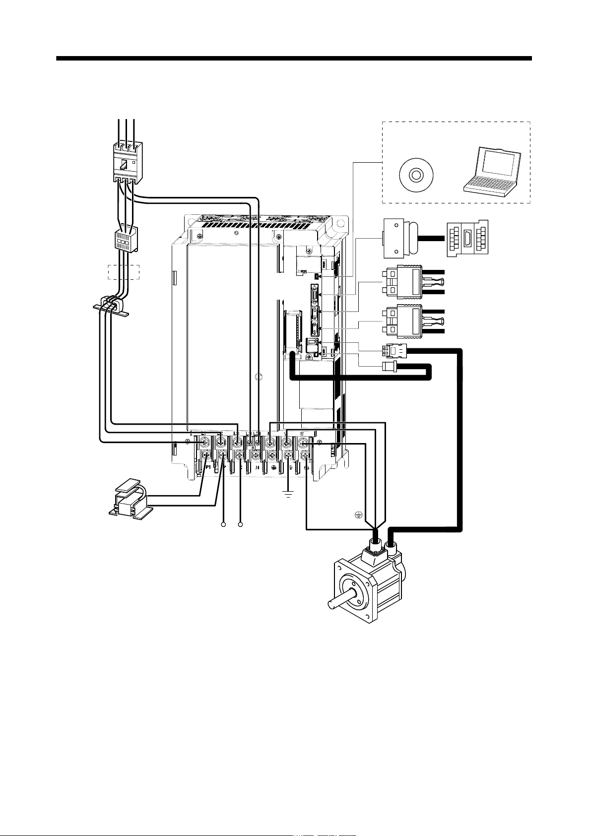
1 - 28
1. FUNCTIONS AND CONFIGURATION
(7) MR-J3-11KB(4) to MR-J3-22KB(4)
Line noise filter
(FR-BLF)
(Note 3)
Power supply
R S T
Magnetic
contactor
(MC)
No-fuse
breaker (NFB)
or fuse
Regenerative option
L
21
Servo amplifier
Servo motor
(Note 2)
L11
UVW
CP
L1
L
2
L3
CN4
MR Configurator
Personal
computer
CN5
CN3
CN2
Junction
terminal
block
Servo system
controller or Front axis
servo amplifier CN1B
Rear servo amplifier
CN1A or Cap
CN1A
CN1B
P1
P
(Note 2)
Power factor improving
DC reactor (FR-BEL-(H))
(Note 1)
Battery
MR-J3BAT
Note 1. The battery (option) is used for the absolute position detection system in the position control mode.
2. The AC reactor can also be used. In this case, the DC reactor cannot be used. When not using DC reactor, short P
1 and P.
3. Refer to section 1.3 for the power supply specification.
2 - 1
2. INSTALLATION
2. INSTALLATION
CAUTION
Stacking in excess of the limited number of products is not allowed.
Install the equipment on incombustible material. Installing them directly or close to
combustibles will lead to a fire.
Install the equipment in a load-bearing place in accordance with this Instruction
Manual.
Do not get on or put heavy load on the equipment to prevent injury.
Use the equipment within the specified environmental condition range. (For the
environmental conditions, refer to section 1.3.)
Provide an adequate protection to prevent screws, metallic detritus and other
conductive matter or oil and other combustible matter from entering the servo
amplifier.
Do not block the intake/exhaust ports of the servo amplifier. Otherwise, a fault may
occur.
Do not subject the servo amplifier to drop impact or shock loads as they are
precision equipment.
Do not install or operate a faulty servo amplifier.
When the product has been stored for an extended period of time, consult
Mitsubishi.
When treating the servo amplifier, be careful about the edged parts such as the
corners of the servo amplifier.
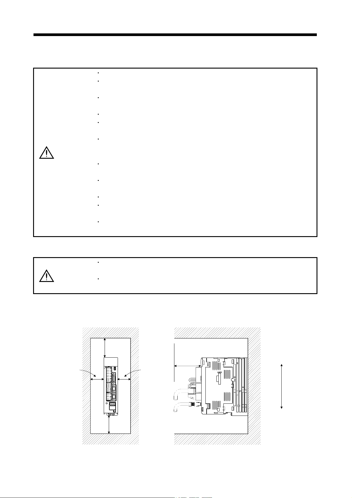
2.1 Installation direction and clearances
CAUTION
The equipment must be installed in the specified direction. Otherwise, a fault may
occur.
Leave specified clearances between the servo amplifier and control box inside
walls or other equipment.
(1) 7kW or less
(a) Installation of one servo amplifier
40mm
or more
Servo amplifier
40mm
or more
Control box
10mm
or more
10mm
or more
Wiring allowance
80mm
Top
Bottom
Control box