sh030051g.pdf - 第27页
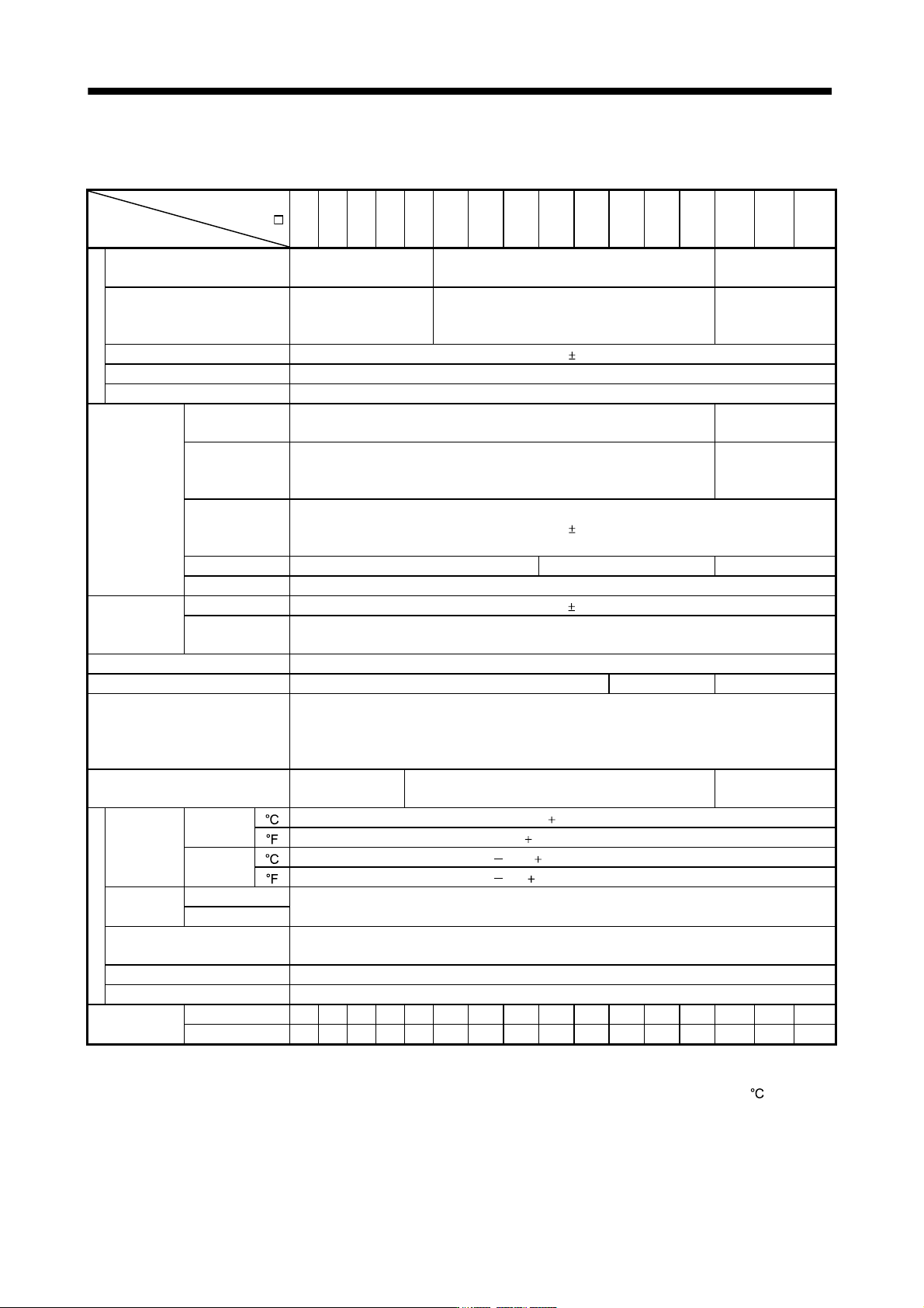
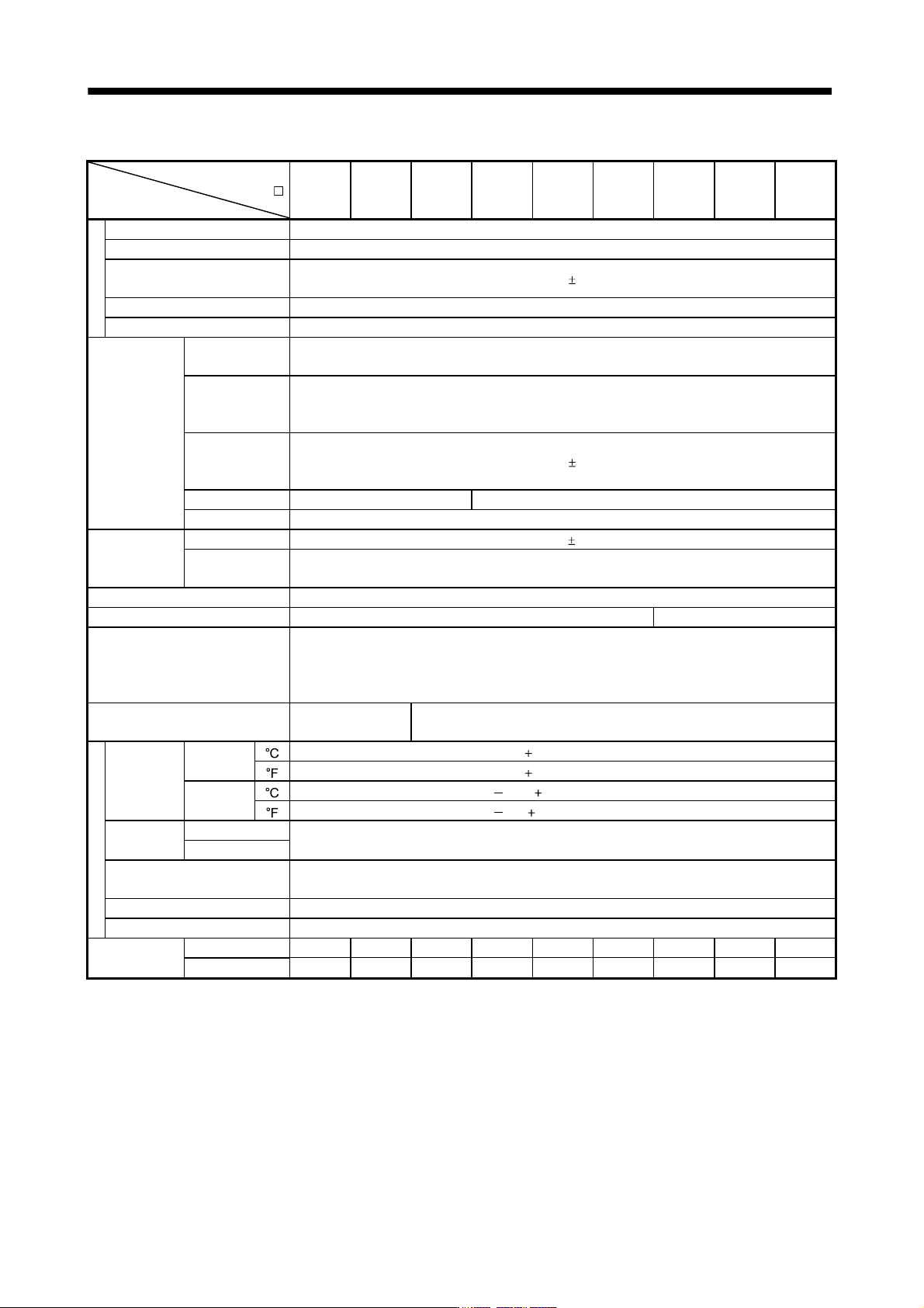
1 - 6 1. FUNCTIONS AND CONFIGURATIO N (2) 400V class Servo amplifier MR-J3- Item 60B4 100B4 200B4 350B4 500B4 700B4 11KB4 15KB4 22KB4 Power su pp l y Voltage/frequ ency 3-phase 380 to 480VA C, 50/60Hz Permissible voltage…
1 - 5
1. FUNCTIONS AND CONFIGURATION
1.3 Servo amplifier standard specifications
(1) 200V class, 100V class
Servo amplifier
MR-J3-
Item
10B 20B 40B 60B 70B 100B 200B 350B 500B 700B 11KB 15KB 22KB 10B1 20B1 40B1
Power su
pp
l
y
Voltage/frequency
3-phase or 1-phase 200
to 230VAC, 50/60Hz
3-phase 200 to 230VAC, 50/60Hz
1-phase 100V to
120VAC, 50/60Hz
Permissible voltage fluctuation
3-phase or 1-phase 200
to 230VAC: 170 to
253VAC
3-phase 170 to 253VAC
1-phase 85 to
132VAC
Permissible frequency fluctuation Within 5%
Power supply capacity Refer to section 10.2
Inrush current Refer to section 10.5
Control circuit
power supply
Voltage,
frequency
1-phase 200 to 230VAC, 50/60Hz
1-phase 100 to
120VAC, 50/60Hz
Permissible
voltage
fluctuation
1-phase 170 to 253VAC
1-phase 85 to
132VAC
Permissible
frequency
fluctuation
Within
5%
Input 30W 45W 30W
Inrush current Refer to section 10.5
Interface power
supply
Voltage 24VDC
10%
Power supply
capacity
(Note 1) 150mA or more
Control System Sine-wave PWM control, current control system
Dynamic brake Built-in External option Built-in
Protective functions
Overcurrent shut-off, regenerative overvoltage shut-off, overload shut-off (electronic thermal relay),
servo motor overheat protection, encoder error protection, regenerative error protection,
undervoltage, instantaneous power failure protection, overspeed protection, excessive error
protection.
Structure
Self-cooled, open
(IP00)
Force-cooling, open (IP00)
Self-cooled, open
(IP00)
Environment
Ambient
temperature
In
operation
[
] (Note 2) 0 to 55 (non-freezing)
[ ] 32 to 131 (non-freezing)
In storage
[
] 20 to 65 (non-freezing)
[ ] 4 to 149 (non-freezing)
Ambient
humidity
In operation
90%RH or less (non-condensing)
In storage
Ambient
Indoors (no direct sunlight)
Free from corrosive gas, flammable gas, oil mist, dust and dirt
Altitude Max. 1000m above sea level
Vibration 5.9 [m/s
2
] or less
Mass
[kg] 0.8 0.8 1.0 1.0 1.4 1.4 2.1 2.3 4.6 6.2 18 18 19 0.8 0.8 1.0
[lb] 1.76 1.76 2.21 2.21 3.09 3.09 4.63 5.07 10.1 13.7 39.7 39.7 41.9 1.76 1.76 2.21
Note 1. 150mA is the value applicable when all I/O signals are used. The current capacity can be decreased by reducing the number of
I/O points.
2. When closely mounting the servo amplifier of 3.5kW or less, operate them at the ambient temperatures of 0 to 45
or at 75% or
smaller effective load ratio.
1 - 6
1. FUNCTIONS AND CONFIGURATION
(2) 400V class
Servo amplifier
MR-J3-
Item
60B4 100B4 200B4 350B4 500B4 700B4 11KB4 15KB4 22KB4
Power su
pp
l
y
Voltage/frequency 3-phase 380 to 480VAC, 50/60Hz
Permissible voltage fluctuation 3-phase 323 to 528VAC
Permissible frequency
fluctuation
Within
5%
Power supply capacity Refer to section 10.2
Inrush current Refer to section 10.5
Control circuit
power supply
Voltage,
frequency
1-phase 380 to 480VAC, 50/60Hz
Permissible
voltage
fluctuation
1-phase 323 to 528VAC
Permissible
frequency
fluctuation
Within
5%
Input 30W 45W
Inrush current Refer to section 10.5
Interface power
supply
Voltage 24VDC
10%
Power supply
capacity
(Note) 150mA
Control System Sine-wave PWM control, current control system
Dynamic brake Built-in External option
Protective functions
Overcurrent shut-off, regenerative overvoltage shut-off, overload shut-off (electronic thermal relay),
servo motor overheat protection, encoder error protection, regenerative error protection,
undervoltage, instantaneous power failure protection, overspeed protection, excessive error
protection.
Structure
Self-cooled, open
(IP00)
Force-cooling, open (IP00)
Environment
Ambient
temperature
In
operation
[
] 0 to 55 (non-freezing)
[ ] 32 to 131 (non-freezing)
In storage
[
] 20 to 65 (non-freezing)
[ ] 4 to 149 (non-freezing)
Ambient
humidity
In operation
90%RH or less (non-condensing)
In storage
Ambient
Indoors (no direct sunlight)
Free from corrosive gas, flammable gas, oil mist, dust and dirt
Altitude Max. 1000m above sea level
Vibration 5.9 [m/s
2
] or less
Mass
[kg] 1.7 1.7 2.1 4.6 4.6 6.2 18 18 19
[lb] 3.75 3.75 4.63 10.14 10.14 13.67 39.68 39.68 41.88
Note. 150mA is the value applicable when all I/O signals are used. The current capacity can be decreased by reducing the number of
I/O points.
1 - 7
1. FUNCTIONS AND CONFIGURATION
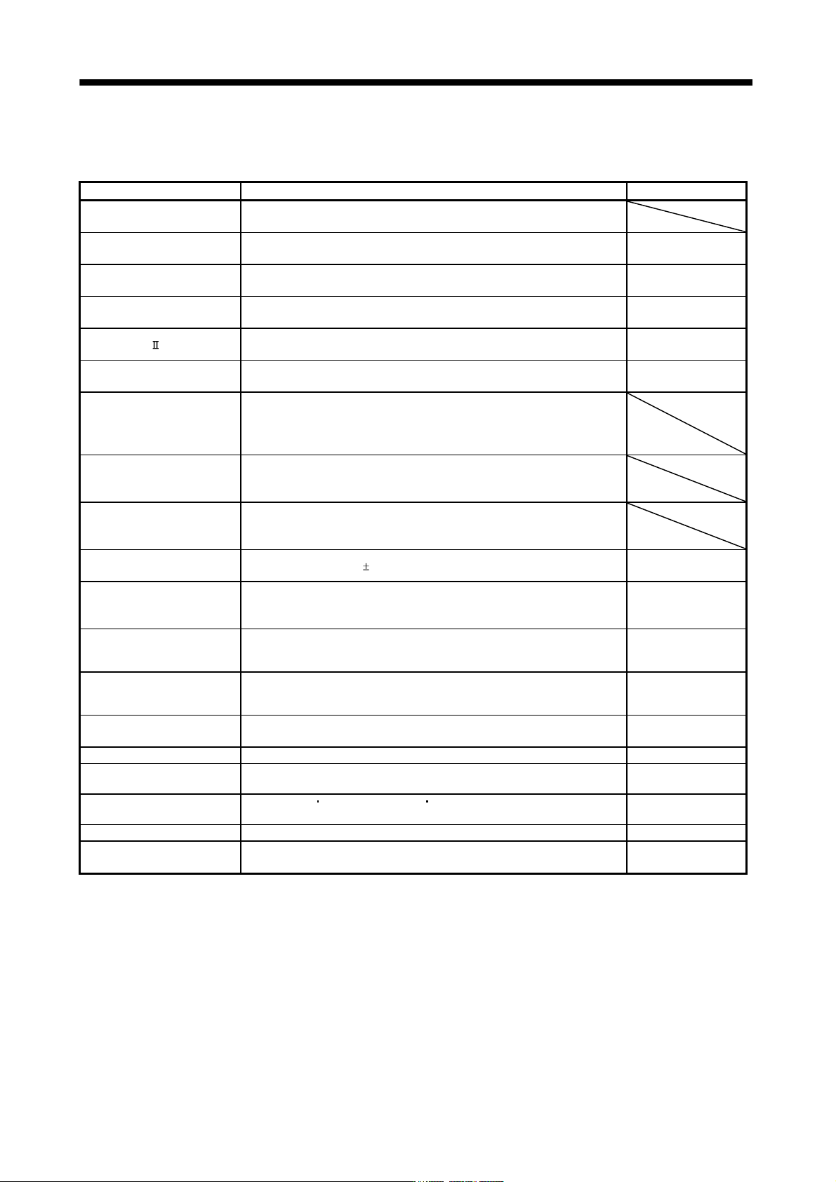
1.4 Function list
The following table lists the functions of this servo. For details of the functions, refer to the reference field.
Function Description Reference
High-resolution encoder
High-resolution encoder of 262144 pulses/rev is used as a servo motor
encoder.
Absolute position detection
system
Merely setting a home position once makes home position return
unnecessary at every power-on.
Chapter 12
Gain changing function
You can switch between gains during rotation and gains during stop or use
an input device to change gains during operation.
Section 7.6
Advanced vibration
suppression control
This function suppresses vibration at the arm end or residual vibration. Section 7.4
Adaptive filter
Servo amplifier detects mechanical resonance and sets filter characteristics
automatically to suppress mechanical vibration.
Section 7.2
Low-pass filter
Suppresses high-frequency resonance which occurs as servo system
response is increased.
Section 7.5
Machine analyzer function
Analyzes the frequency characteristic of the mechanical system by simply
connecting a MR Configurator installed personal computer and servo
amplifier.
MR Configurator is necessary for this function.
Machine simulation
Can simulate machine motions on a personal computer screen on the basis
of the machine analyzer results.
MR Configurator is necessary for this function.
Gain search function
Personal computer changes gains automatically and searches for overshoot-
free gains in a short time.
MR Configurator is necessary for this function.
Slight vibration suppression
control
Suppresses vibration of
1 pulse produced at a servo motor stop. Parameters No.PB24
Auto tuning
Automatically adjusts the gain to optimum value if load applied to the servo
motor shaft varies. Higher in performance than MR-J2-Super series servo
amplifier.
Chapter 6
Brake unit
Used when the regenerative option cannot provide enough regenerative
power.
Can be used the 5kW or more servo amplifier.
Section 11.3
Return converter
Used when the regenerative option cannot provide enough regenerative
power.
Can be used the 5kW or more servo amplifier.
Section 11.4
Regenerative option
Used when the built-in regenerative resistor of the servo amplifier does not
have sufficient regenerative capability for the regenerative power generated.
Section 11.2
Alarm history clear Alarm history is cleared. Parameter No.PC21
Output signal (DO)
forced output
Output signal can be forced on/off independently of the servo status.
Use this function for output signal wiring check, etc.
Section 4.5.1 (1) (d)
Test operation mode
JOG operation
positioning operation DO forced output.
However, MR Configurator is necessary for positioning operation.
Section 4.5
Analog monitor output Servo status is output in terms of voltage in real time. Parameter No.PC09
MR Configurator
Using a personal computer, parameter setting, test operation, status display,
etc. can be performed.
Section 11.8