sh030051g.pdf - 第51页
2 - 2 2. INSTALLATION (b) Installation of two or more servo amplifiers POINT Close mounting is availabl e for the servo amplifier of under 3.5kW for 200V class and 400W for 1 00V class. Leave a large clearance between th…
2 - 1
2. INSTALLATION
2. INSTALLATION
CAUTION
Stacking in excess of the limited number of products is not allowed.
Install the equipment on incombustible material. Installing them directly or close to
combustibles will lead to a fire.
Install the equipment in a load-bearing place in accordance with this Instruction
Manual.
Do not get on or put heavy load on the equipment to prevent injury.
Use the equipment within the specified environmental condition range. (For the
environmental conditions, refer to section 1.3.)
Provide an adequate protection to prevent screws, metallic detritus and other
conductive matter or oil and other combustible matter from entering the servo
amplifier.
Do not block the intake/exhaust ports of the servo amplifier. Otherwise, a fault may
occur.
Do not subject the servo amplifier to drop impact or shock loads as they are
precision equipment.
Do not install or operate a faulty servo amplifier.
When the product has been stored for an extended period of time, consult
Mitsubishi.
When treating the servo amplifier, be careful about the edged parts such as the
corners of the servo amplifier.
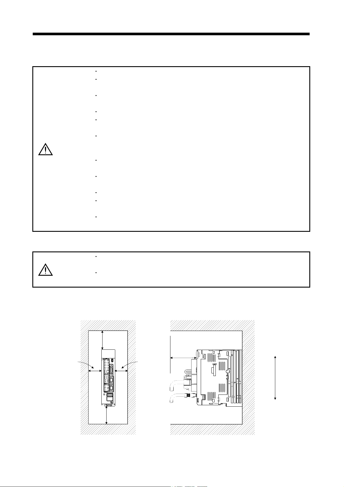
2.1 Installation direction and clearances
CAUTION
The equipment must be installed in the specified direction. Otherwise, a fault may
occur.
Leave specified clearances between the servo amplifier and control box inside
walls or other equipment.
(1) 7kW or less
(a) Installation of one servo amplifier
40mm
or more
Servo amplifier
40mm
or more
Control box
10mm
or more
10mm
or more
Wiring allowance
80mm
Top
Bottom
Control box
2 - 2
2. INSTALLATION
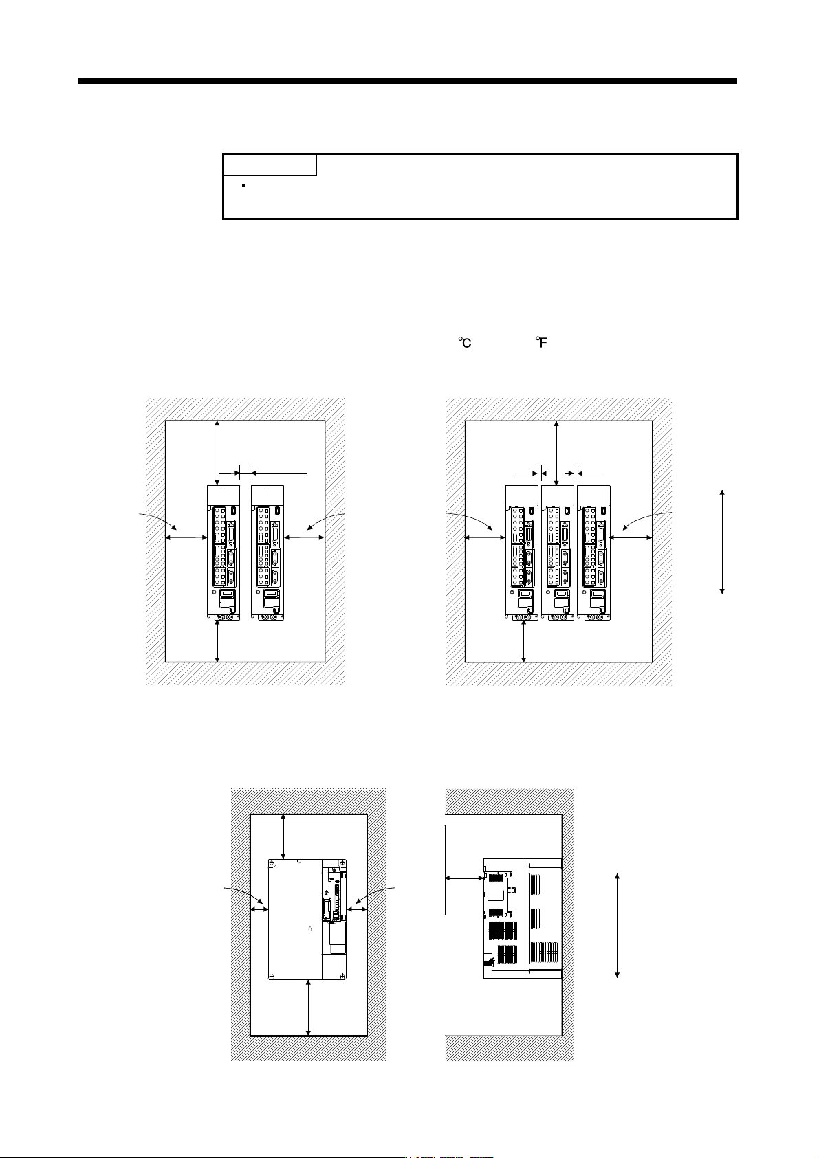
(b) Installation of two or more servo amplifiers
POINT
Close mounting is available for the servo amplifier of under 3.5kW for 200V
class and 400W for 100V class.
Leave a large clearance between the top of the servo amplifier and the internal surface of the control
box, and install a cooling fan to prevent the internal temperature of the control box from exceeding the
environmental conditions.
When installing the servo amplifiers closely, leave a clearance of 1mm between the adjacent servo
amplifiers in consideration of mounting tolerances.
In this case, bring the ambient temperature within 0 to 45
(32 to 113 ), or use it at 75% or smaller
effective load ratio.
40mm or more
Control box
30mm
or more
30mm
or more
Control box
Leaving clearance
Mounting closely
30mm
or more
1mm 1mm
100mm
or more
30mm
or more
100mm
or more
10mm
or more
40mm
or more
Top
Bottom
(2) 11k to 22kW
(a) Installation of one servo amplifier
40mm or more
10mm
or more
120mm
or more
Wiring allowance
80mm
Top
Bottom
Servo amplifier
Control box
Control box
10mm
or more
2 - 3
2. INSTALLATION
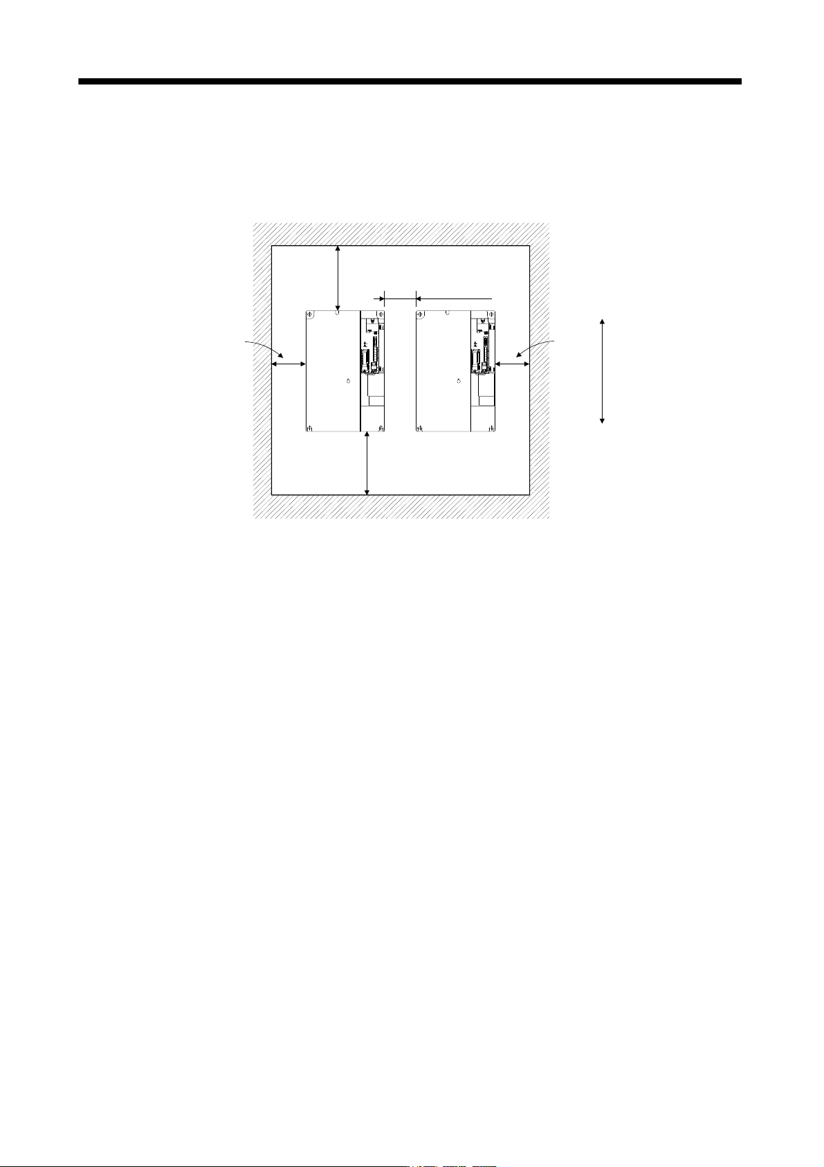
(b) Installation of two or more servo amplifiers
Leave a large clearance between the top of the servo amplifier and the internal surface of the control
box, and install a cooling fan to prevent the internal temperature of the control box from exceeding the
environmental conditions.
100mm
or more
30m
or more
120mm or more
30mm
or more
10mm or more
Control box
Top
Bottom
(3) Others
When using heat generating equipment such as the regenerative option, install them with full consideration
of heat generation so that the servo amplifier is not affected.
Install the servo amplifier on a perpendicular wall in the correct vertical direction.
2.2 Keep out foreign materials
(1) When installing the unit in a control box, prevent drill chips and wire fragments from entering the servo
amplifier.
(2) Prevent oil, water, metallic dust, etc. from entering the servo amplifier through openings in the control box or
a cooling fan installed on the ceiling.
(3) When installing the control box in a place where there are much toxic gas, dirt and dust, conduct an air
purge (force clean air into the control box from outside to make the internal pressure higher than the
external pressure) to prevent such materials from entering the control box.
2.3 Cable stress
(1) The way of clamping the cable must be fully examined so that flexing stress and cable's own weight stress
are not applied to the cable connection.
(2) For use in any application where the servo motor moves, fix the cables (encoder, power supply, brake) with
having some slack from the connector connection part of the servo motor to avoid putting stress on the
connector connection part. Use the optional encoder cable within the flexing life range. Use the power
supply and brake wiring cables within the flexing life of the cables.