sh030051g.pdf - 第227页
11 - 22 11. OPTIONS AND AUXILI ARY EQUIPMENT (2) Selection of the regenerative option Use the following method when regenerat ion occurs continuously in vertic al motion applications or when it is desired to make an in-d…
11 - 21
11. OPTIONS AND AUXILIARY EQUIPMENT
11.2 Regenerative options
CAUTION
The specified combinations of regenerative options and servo amplifiers may only
be used. Otherwise, a fire may occur.
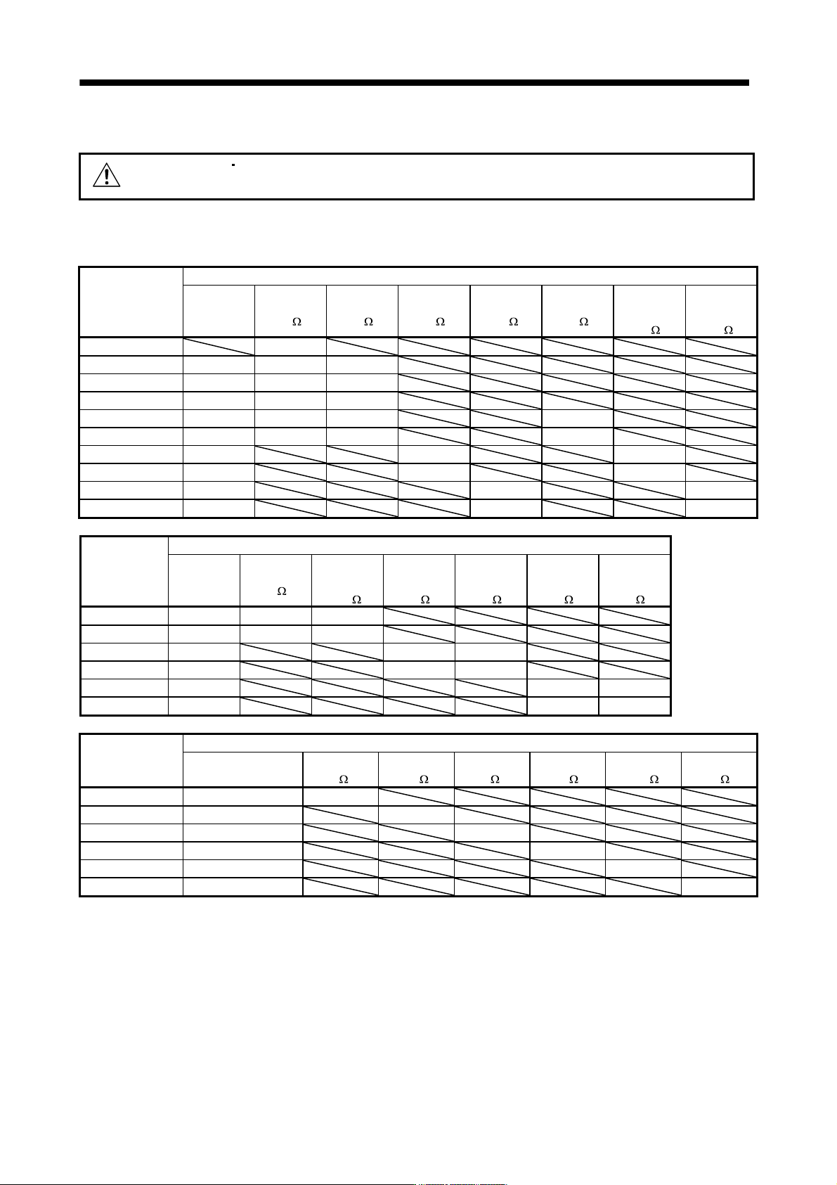
(1) Combination and regenerative power
The power values in the table are resistor-generated powers and not rated powers.
Servo amplifier
Regenerative power[W]
Built-in
regenerative
resistor
MR-RB032
[40
]
MR-RB12
[40 ]
MR-RB30
[13 ]
MR-RB31
[6.7 ]
MR-RB32
[40 ]
(Note 1)
MR-RB50
[13
]
(Note 1)
MR-MB51
[6.7
]
MR-J3-10B (1) 30
MR-J3-20B (1) 10 30 100
MR-J3-40B (1) 10 30 100
MR-J3-60B 10 30 100
MR-J3-70B 20 30 100 300
MR-J3-100B 20 30 100 300
MR-J3-200B 100 300 500
MR-J3-350B 100 300 500
MR-J3-500B 130 300 500
MR-J3-700B 170 300 500
Servo amplifier
Regenerative power[W]
Built-in
regenerative
resistor
MR-RB1H-4
[82
]
(Note 1)
MR-RB3M-4
[120
]
(Note 1)
MR-RB3G-4
[47
]
(Note 1)
MR-RB5G-4
[47
]
(Note 1)
MR-RB34-4
[26
]
(Note 1)
MR-RB54-4
[26
]
MR-J3-60B4 15 100 300
MR-J3-100B4 15 100 300
MR-J3-200B4 100 300 500
MR-J3-350B4 100 300 500
MR-J3-500B4 130 300 500
MR-J3-700B4 170 300 500
Servo amplifier
(Note 2) Regenerative power[W]
External regenerative
resistor (Accessory)
MR-RB5E
[6
]
MR-RB9P
[4.5 ]
MR-RB9F
[3 ]
MR-RB6B-4
[20 ]
MR-RB60-4
[12.5 ]
MR-RB6K-4
[10 ]
MR-J3-11KB 500 (800) 500 (800)
MR-J3-15KB 850 (1300) 850 (1300)
MR-J3-22KB 850 (1300) 850 (1300)
MR-J3-11KB4 500 (800) 500 (800)
MR-J3-15KB4 850 (1300) 850 (1300)
MR-J3-22KB4 850 (1300) 850 (1300)
Note 1. Always install a cooling fan.
2. Values in parentheses assume the installation of a cooling fan.
11 - 22
11. OPTIONS AND AUXILIARY EQUIPMENT
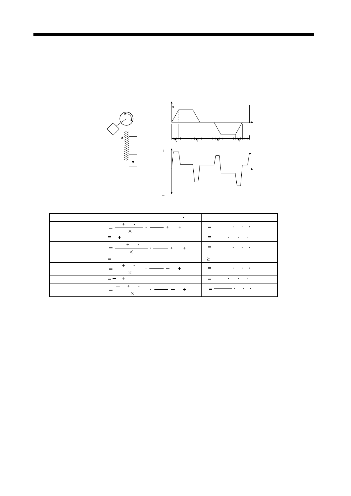
(2) Selection of the regenerative option
Use the following method when regeneration occurs continuously in vertical motion applications or when it
is desired to make an in-depth selection of the regenerative option.
(a) Regenerative energy calculation
Use the following table to calculate the regenerative energy.
M
Friction
torque
U
n
b
a
l
a
n
c
e
t
o
r
q
u
e
TF
T
U
S
e
r
v
o
m
o
t
o
r
s
p
e
e
d
G
e
n
e
r
a
t
e
d
t
o
r
q
u
e
Time
Up
No
tf(1 cycle)
Down
( )
( )
(Driving)
(Regenerative)
Tpsd2
t2 t3 t4t1
T
psa2Tpsd1
T
psa1
1)
2)
3)
4)
5)
6)
7)
8)
Formulas for calculating torque and energy in operation
Regenerative power Torque applied to servo motor [N m] Energy [J]
1)
T
1
(J
L
J
M
)
9.55
10
4
N0
1
T
psa1
T
U
T
F
E
1
2
0.1047
N
0
T1 Tpsa1
2)
T
2
T
U
T
F
E
2
0.1047 N
0
T
2
t
1
3)
T
3
(JL JM)
9.55
10
4
N0
1
Tpsd1
TU TF
E
3
2
0.1047
N
0
T
3
T
psd1
4), 8)
T
4
T
U
E
4
0 (No regeneration)
5)
T5
(J
L
J
M
)
9.55
10
4
N0
1
Tpsa2
TU TF
E
5
2
0.1047
N
0
T5 Tpsa2
6)
T
6
T
U
T
F
E
6
0.1047 N
0
T
6
t
3
7)
T
7
(JL JM)
9.55
10
4
N0
1
Tpsd2
TU TF
E7
2
0.1047
N
0
T
7
T
psd2
From the calculation results in 1) to 8), find the absolute value (Es) of the sum total of negative energies.
11 - 23
11. OPTIONS AND AUXILIARY EQUIPMENT
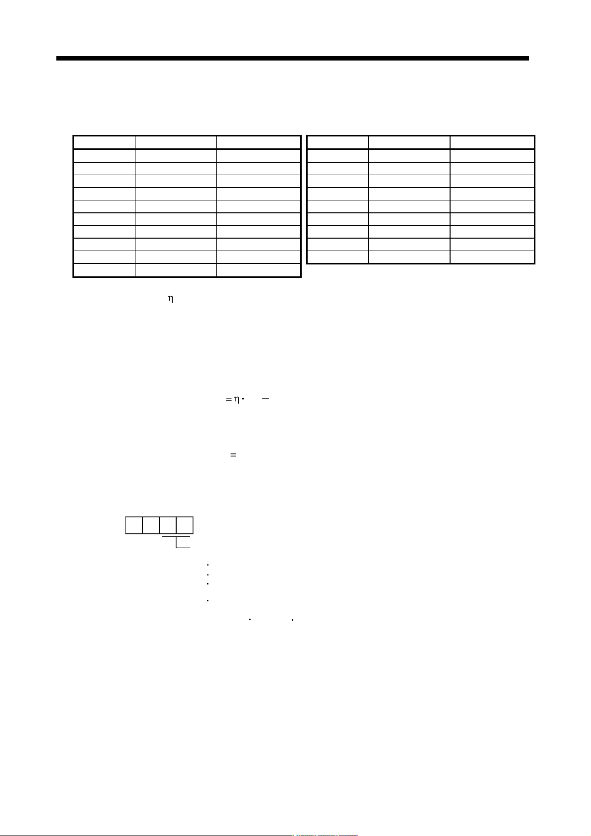
(b) Losses of servo motor and servo amplifier in regenerative mode
The following table lists the efficiencies and other data of the servo motor and servo amplifier in the
regenerative mode.
Servo amplifier Inverse efficiency[%] Capacitor charging[J] Servo amplifier Inverse efficiency[%] Capacitor charging[J]
MR-J3-10B 55 9 MR-J3-200B 85 40
MR-J3-10B1 55 4 MR-J3-200B4 85 25
MR-J3-20B 70 9 MR-J3-350B 85 40
MR-J3-20B1 70 4 MR-J3-350B4 85 36
MR-J3-40B 85 11 MR-J3-500B(4) 90 45
MR-J3-40B1 85 10 MR-J3-700B(4) 90 70
MR-J3-60B(4) 85 11 MR-J3-11KB(4) 90 120
MR-J3-70B 80 18 MR-J3-15KB(4) 90 170
MR-J3-100B 80 18 MR-J3-22KB(4) 90 250
MR-J3-100B4 80 12
Inverse efficiency (
) : Efficiency including some efficiencies of the servo motor and servo amplifier
when rated (regenerative) torque is generated at rated speed. Since the
efficiency varies with the speed and generated torque, allow for about 10%.
Capacitor charging (Ec) : Energy charged into the electrolytic capacitor in the servo amplifier.
Subtract the capacitor charging from the result of multiplying the sum total of regenerative energies by
the inverse efficiency to calculate the energy consumed by the regenerative option.
ER [J]
Es Ec
Calculate the power consumption of the regenerative option on the basis of single-cycle operation
period tf [s] to select the necessary regenerative option.
PR [W]
ER/tf
(3) Parameter setting
Set parameter No.PA02 according to the option to be used.
Selection of regenerative option
00: Regenerative option is not used
For servo amplifier of 100W, regenerative resistor is not used.
For servo amplifier of 200 to 7kW, built-in regenerative resistor is used.
Supplied regenerative resistors or regenerative option is used with
the servo amplifier of 11k to 22kW.
For a drive unit of 30kW or more, select regenerative option by the
converter unit.
01: FR-BU2-(H) FR-RC-(H) FR-CV-(H)
02: MR-RB032
03: MR-RB12
04: MR-RB32
05: MR-RB30
06: MR-RB50(Cooling fan is required)
08: MR-RB31
09: MR-RB51(Cooling fan is required)
80: MR-RB1H-4
81: MR-RB3M-4(Cooling fan is required)
82: MR-RB3G-4(Cooling fan is required)
83: MR-RB5G-4(Cooling fanis required)
84: MR-RB34-4(Cooling fanis required)
85: MR-RB54-4(Cooling fanis required)
FA: Whenhe supplied regenerative resistor is cooled by the cooling fan to
increase the ability with the servo amplifier of 11k to 22kW.
00
Parameter No.PA02