sh030051g.pdf - 第281页
11 - 76 11. OPTIONS AND AUXILI ARY EQUIPMENT 11.16 Surge absorbers (recommended) A surge absorber is required for the electromagnetic br ake. Use the following surge absorber or equivalent. When using the surge absorber,…
11 - 75
11. OPTIONS AND AUXILIARY EQUIPMENT
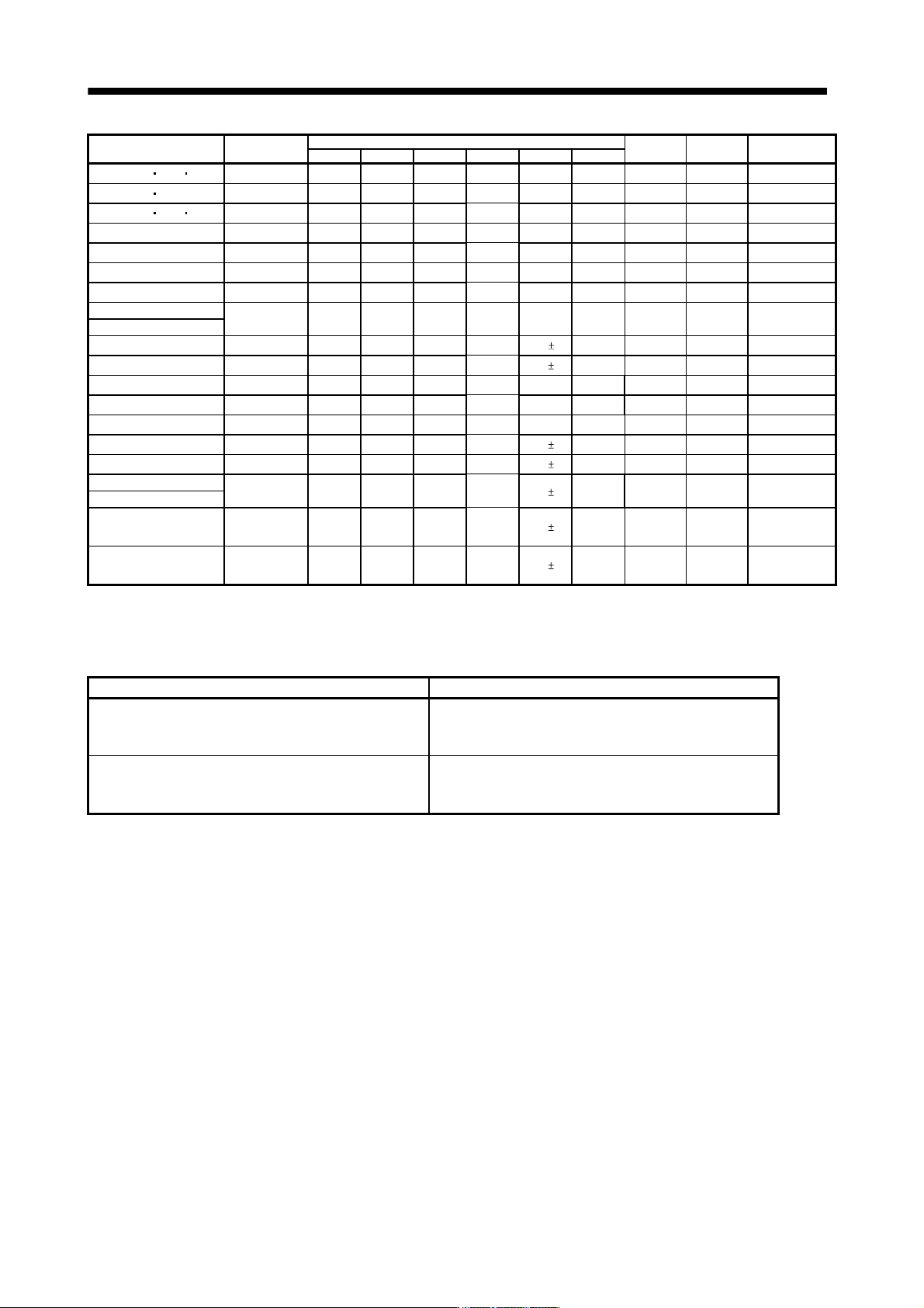
Servo amplifier Model
Dimensions [mm]
Mounting
screw size
Terminal
screw size
Mass
[kg (lb)]
W W1 H D D1 C
MR-J3-10B 20B 10B1
FR-BAL-0.4K
135 120 115 59 45
0
-2.5
7.5 M4 M3.5 2.0 (4.41)
MR-J3-40B 20B1
FR-BAL-0.75K
135 120 115 69 57
0
-2.5
7.5 M4 M3.5 2.8 (6.17)
MR-J3-60B 70B 40B1
FR-BAL-1.5K
160 145 140 71 55
0
-2.5
7.5 M4 M3.5 3.7 (8.16)
MR-J3-100B
FR-BAL-2.2K
160 145 140 91 75
0
-2.5
7.5 M4 M3.5 5.6 (12.35)
MR-J3-200B
FR-BAL-3.7K
220 200 192 90 70
0
-2.5
10 M5 M4 8.5 (18.74)
MR-J3-350B
FR-BAL-7.5K
220 200 194 120 100
0
-2.5
10 M5 M5 14.5 (31.97)
MR-J3-500B
FR-BAL-11K
280 255 220 135 100
0
-2.5
12.5 M6 M6 19 (41.89)
MR-J3-700B
FR-BAL-15K
295 270 275 133 110
0
-2.5
12.5 M6 M6 27 (59.53)
MR-J3-11KB
MR-J3-15KB
FR-BAL-22K
290 240 301 199
170
5
25 M8 M8 35 (77.16)
MR-J3-22KB
FR-BAL-30K
290 240 301 219
190
5
25 M8 M8 43 (94.80)
MR-J3-60B4
FR-BAL-H1.5K
160 145 140 87 70
0
-2.5
7.5 M4 M3.5 5.3 (11.68)
MR-J3-100B4
FR-BAL-H2.2K
160 145 140 91 75
0
-2.5
7.5 M4 M3.5 5.9 (13.01)
MR-J3-200B4
FR-BAL-H3.7K
220 200 190 90 70
0
-2.5
10 M5 M3.5 8.5 (18.74)
MR-J3-350B4
FR-BAL-H7.5K
220 200 192 120
100
5
10 M5 M4 14 (30.87)
MR-J3-500B4
FR-BAL-H11K
280 255 226 130
100
5
12.5 M6 M5 18.5 (40.79)
MR-J3-700B4
FR-BAL-H15K
295 270 244 130
110
5
12.5 M6 M5 27 (59.53)
MR-J3-11KB4
MR-J3-15KB4
FR-BAL-H22K
290 240 269 199
170
5
25 M8 M8
Approx.35
(Approx.77.16)
MR-J3-22KB4
FR-BAL-H30K
290 240 290 219
190
5
25 M8 M8
Approx.43
(Approx.94.80)
11.15 Relays (recommended)
The following relays should be used with the interfaces.
Interface Selection example
Relay used for digital input command signals (interface DI-1) To prevent defective contacts , use a relay for small signal
(twin contacts).
(Ex.) Omron : type G2A , MY
Relay used for digital output signals (interface DO-1) Small relay with 12VDC or 24VDC of rated current 40mA or
less
(Ex.) Omron : type MY
11 - 76
11. OPTIONS AND AUXILIARY EQUIPMENT
11.16 Surge absorbers (recommended)
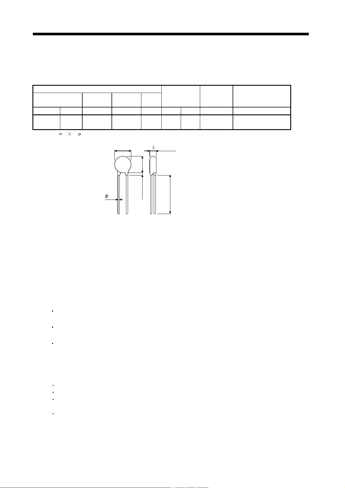
A surge absorber is required for the electromagnetic brake. Use the following surge absorber or equivalent.
When using the surge absorber, perform insulation beforehand to prevent short-circuit.
Maximum rating
Maximum
limit voltage
Static capacity
(reference
value)
Varistor voltage
rating (range) V1mA
Permissible circuit
voltage
Surge
immunity
Energy
immunity
Rated
power
AC[Vma] DC[V] [A] [J] [W] [A] [V] [pF] [V]
140 180
(Note)
500/time
5 0.4 25 360 300
220
(198 to 242)
Note. 1 time 8 20 s
13.5
1
6
.
5
4.7 1.0
0.8
3.0 or less
30.0 or more
[Unit: mm]
(Example) ERZV10D221 (Matsushita Electric Industry)
TNR-10V221K (Nippon chemi-con)
Outline drawing [mm] (ERZ-C10DK221)
11.17 Noise reduction techniques
Noises are classified into external noises which enter the servo amplifier to cause it to malfunction and those
radiated by the servo amplifier to cause peripheral devices to malfunction. Since the servo amplifier is an
electronic device which handles small signals, the following general noise reduction techniques are required.
Also, the servo amplifier can be a source of noise as its outputs are chopped by high carrier frequencies. If
peripheral devices malfunction due to noises produced by the servo amplifier, noise suppression measures
must be taken. The measures will vary slightly with the routes of noise transmission.
(1) Noise reduction techniques
(a) General reduction techniques
Avoid laying power lines (input and output cables) and signal cables side by side or do not bundle
them together. Separate power lines from signal cables.
Use shielded, twisted pair cables for connection with the encoder and for control signal transmission,
and connect the shield to the SD terminal.
Ground the servo amplifier, servo motor, etc. together at one point (refer to section 3.12).
(b) Reduction techniques for external noises that cause the servo amplifier to malfunction
If there are noise sources (such as a magnetic contactor, an electromagnetic brake, and many relays
which make a large amount of noise) near the servo amplifier and the servo amplifier may malfunction,
the following countermeasures are required.
Provide surge absorbers on the noise sources to suppress noises.
Attach data line filters to the signal cables.
Ground the shields of the encoder connecting cable and the control signal cables with cable clamp
fittings.
Although a surge absorber is built into the servo amplifier, to protect the servo amplifier and other
equipment against large exogenous noise and lightning surge, attaching a varistor to the power input
section of the equipment is recommended.
11 - 77
11. OPTIONS AND AUXILIARY EQUIPMENT
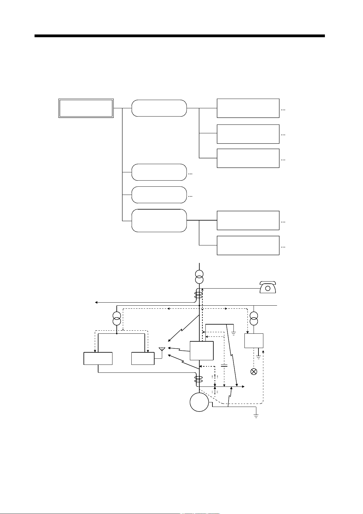
(c) Techniques for noises radiated by the servo amplifier that cause peripheral devices to malfunction
Noises produced by the servo amplifier are classified into those radiated from the cables connected to
the servo amplifier and its main circuits (input and output circuits), those induced electromagnetically or
statically by the signal cables of the peripheral devices located near the main circuit cables, and those
transmitted through the power supply cables.
Noises produced
by servo amplifier
Noises transmitted
in the air
Noise radiated directly
from servo amplifier
Magnetic induction
noise
Static induction
noise
Noises transmitted
through electric
channels
Noise radiated from the
power supply cable
Noise radiated from
servo motor cable
Noise transmitted through
power supply cable
Noise sneaking from
grounding cable due to
leakage current
Routes 4) and 5)
Route 1)
Route 2)
Route 3)
Route 7)
Route 8)
Route 6)
Instrument Receiver
Servo
amplifier
Servo motor M
2)
2)
8)
1)
7)
7) 7)
5)
3)
4)
6)
3)
Sensor
power
supply
Sensor