sh030051g.pdf - 第235页
11 - 30 11. OPTIONS AND AUXILI ARY EQUIPMENT (5) Outline drawing (a) MR-RB032 MR-RB12 [Unit: mm (in)] LA 5 LB TE1 6 6 1 5 6 1 6 8 1 4 4 1 2 A p p r o x . 6 A p p r o x . 1 2 Approx. 20 LD 1.6 LC G3 G4 P C 6 mounting hole…
11 - 29
11. OPTIONS AND AUXILIARY EQUIPMENT
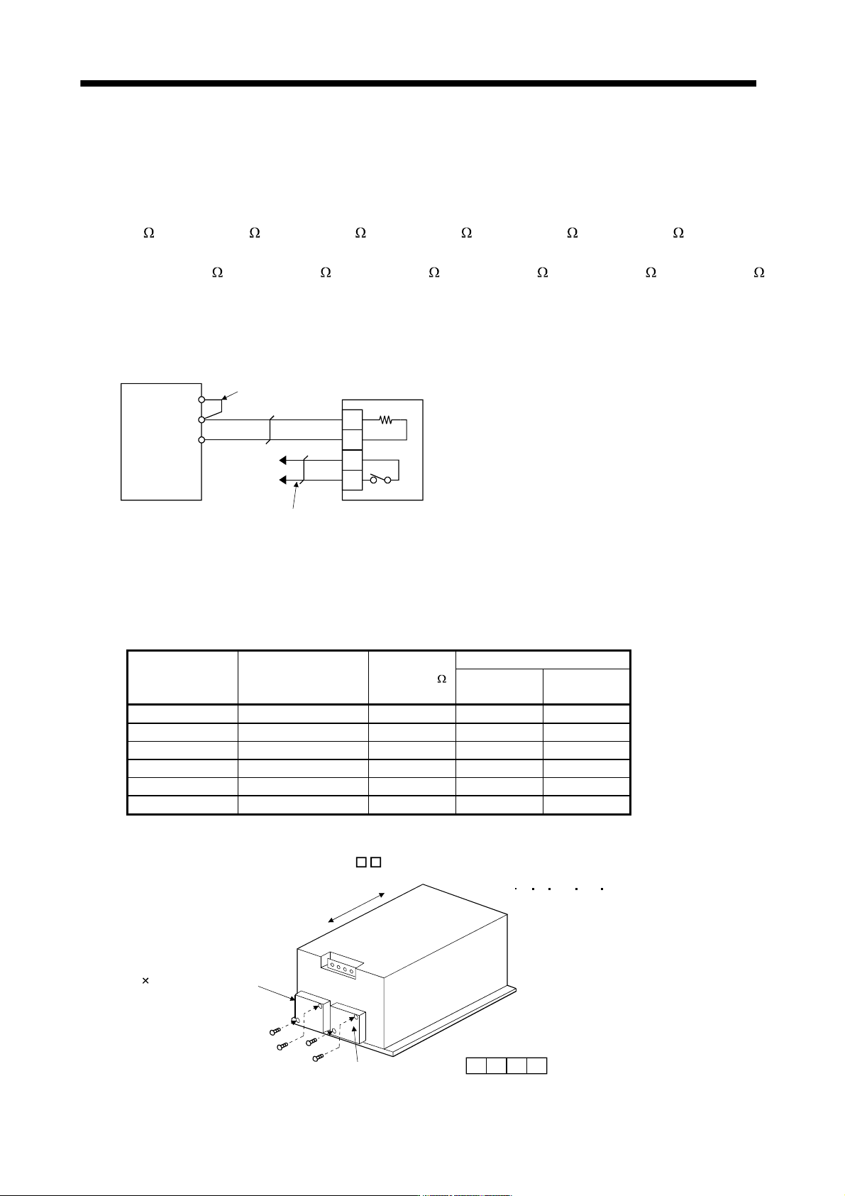
(d) MR-J3-11KB(4)-PX to MR-J3-22KB(4)-PX (when using the regenerative option)
The MR-J3-11KB(4)-PX to MR-J3-22KB(4)-PX servo amplifiers are not supplied with regenerative
resistors. When using any of these servo amplifiers, always use the MR-RB5E, 9P, 9F, 6B-4, 60-4 and
6K-4 regenerative option.
The MR-RB5E, 9P, 9F, 6B-4, 60-4 and 6K-4 are regenerative options that have encased the GRZG400-
1.5
, GRZG400-0.9 , GRZG400-0.6 , GRZG400-5.0 , GRZG400-2.5 , GRZG400-2.0 respectively.
When using any of these regenerative options, make the same parameter setting as when using the
GRZG400-1.5
, GRZG400-0.9 , GRZG400-0.6 , GRZG400-5.0 , GRZG400-2.5 , GRZG400-2.0
(supplied regenerative resistors or regenerative option is used with 11kW or more servo amplifier).
Cooling the regenerative option with cooling fans improves regenerative capability.
The G3 and G4 terminals are for the thermal protector. G3-G4 is opened when the regenerative option
overheats abnormally.
G3
G4
C
P
C
P
P
1
Servo amplifier
Do not remove
the short bar.
Configure up a circuit which
shuts off main circuit power
when thermal protector operates.
(Note)
Regenerative option
Note. Specifications of contact across G3-G4
Maximum voltage : 120V AC/DC
Maximum current : 0.5A/4.8VDC
Maximum capacity : 2.4VA
Servo amplifier
Regenerative option
model
Resistance [ ]
Regenerative power [W]
Without
cooling fans
With
cooling fans
MR-J3-11KB-PX MR-RB5E 6 500 800
MR-J3-15KB-PX MR-RB9P 4.5 850 1300
MR-J3-22KB-PX MR-RB9F 3 850 1300
MR-J3-11KB4-PX MR-RB6B-4 20 500 800
MR-J3-15KB4-PX MR-RB60-4 12.5 850 1300
MR-J3-22KB4-PX MR-RB6K-4 10 850 1300
When using cooling fans, install them using the mounting holes provided in the bottom of the
regenerative option. In this case, set "
FA" in parameter No.PA02.
Mounting screw
4-M3
(92 92, minimum air flow: 1.0m
3
)
MR-RB5E 9P 9F 6B-4 60-4 6K-4
Top
Bottom
TE1
G4 G3 C P
TE
2 cooling fans
11 - 30
11. OPTIONS AND AUXILIARY EQUIPMENT
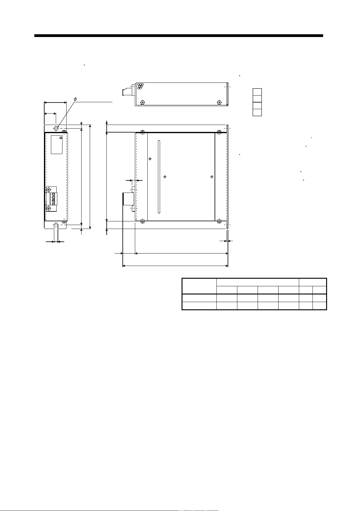
(5) Outline drawing
(a) MR-RB032
MR-RB12
[Unit: mm (in)]
LA
5
LB
TE1
6
6
1
5
6
1
6
8
1
4
4
1
2
A
p
p
r
o
x
.
6
A
p
p
r
o
x
.
1
2
Approx. 20
LD
1.6
LC
G3
G4
P
C
6 mounting hole
MR-RB
TE1
Terminal block
G3
G4
P
C
Terminal screw: M3
Tightening torque: 0.5 to 0.6 [N
m]
(4 to 5 [lb
in])
Mounting screw
Screw size: M5
Tightening torque: 3.24 [N
m]
(28.7 [lb
in])
Regenerative
option
Variable dimensions Mass
LA LB LC LD [kg] [lb]
MR-RB032 30 15 119 99 0.5 1.1
MR-RB12 40 15 169 149 1.1 2.4
11 - 31
11. OPTIONS AND AUXILIARY EQUIPMENT
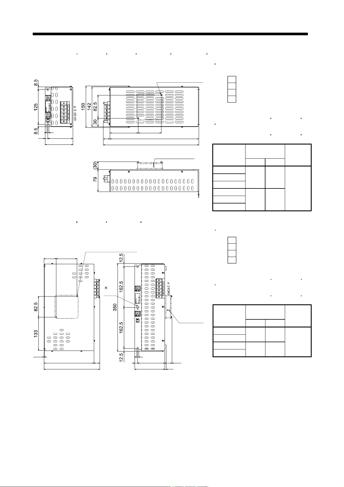
(b) MR-RB30
MR-RB31 MR-RB32 MR-RB34-4 MR-RB3M-4 MR-RB3G-4
[Unit: mm (in)]
7
10 90
100
B
A
318
82.5101.5
Cooling fan mounting
screw (2-M4 screw)
Wind blows in the
arrow direction
TE1
Terminal block
G3
G4
P
C
Terminal screw: M4
Tightening torque: 1.2 [N
m] (10.62 [lb in])
Mounting screw
Screw size: M6
Tightening torque: 5.4 [N
m] (47.79 [lb in])
Regenerative
option
Variable
dimensions
Mass
[kg] (Ib)
A B
MR-RB30
MR-RB31 17 335
MR-RB32
2.9 (6.4)
MR-RB34-4
MR-RB3M-4 23 341
MR-RB3G-4
(c) MR-RB50
MR-RB51 MR-RB54-4 MR-RB5G-4
[Unit: mm (in)]
2.3
49 82.5
200 A
B
8120
10812
7
(30)
7 14
slot
Cooling fan mounting
screw (2-M3 screw)
On opposite side
Wind blows
in the arrow
direction
Terminal block
G3
G4
P
C
Terminal screw: M4
Tightening torque: 1.2 [N
m] (10.62 [lb in])
Mounting screw
Screw size: M6
Tightening torque: 5.4 [N
m] (47.79 [lb in])
Regenerative
option
Variable
dimensions
Mass
[kg] (Ib)
A B
MR-RB50
17 217
MR-RB51
5.6 (12.3)
MR-RB54-4
23 233
MR-RB5G-4