sh030051g.pdf - 第370页
13 - 69 13. SERVO AMPLIFIERS WI TH A LARGE CAPACITY ( 30k TO 55kW ) 13.8.3 Dynamic brake characteristics (1) Dynamic brake operation (a) Calculation of coasting distance Fig. 13.2 shows the pattern in which the servo mot…
13 - 68
13. SERVO AMPLIFIERS WITH A LARGE CAPACITY
(
30k TO 55kW
)
13.8.2 Power supply equipment capacity and generated loss
POINT
The calculation method of heat dissipation area for enclosed control panel is
the same as that for servo amplifiers with 22kW or less. Refer to section 10.2
(2).
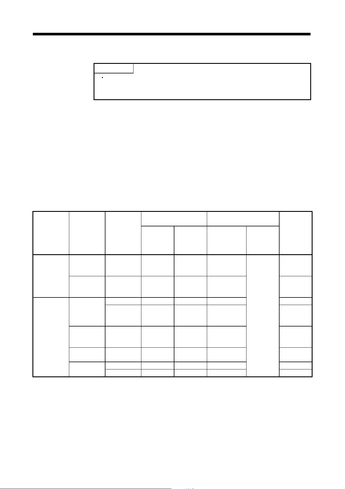
Table 13.1 indicates the generated loss and power supply capacity under rated load per combination of the
converter unit and drive unit. When the servo motors is run at less than the maximum speed, the power supply
equipment capacity is lower than the value in the table but the heat generated does not change.
Since the servo motor requires 2 to 2.5 times greater instantaneous power for acceleration, use the power
supply which ensures that the voltage lies within the permissible voltage fluctuation at the main circuit power
supply terminals (L
1
, L
2
, L
3
) of the converter unit. The power supply equipment capacity changes with the power
supply impedance.
The actually generated heat falls within the ranges at rated torque and at zero torque according to the
frequencies of use during operation. When designing an enclosed control box, use the values in the table,
considering the worst operating conditions. The generated heat in Table 13.1 does not include heat produced
during regeneration.
Table 13.1 Power supply capacity and generated heat per servo amplifier at rated output
Converter unit Drive unit Servo motor
Power supply
capacity [kVA]
(Note)
Drive unit-generated heart[W]
Area required
for heat
dissipation
[m
2
]
Power factor
improving DC
reactor is not
used
Power factor
improving DC
reactor is used
At rated torque At zero torque
MR-J3-CR55K
MR-J3-DU30KB
HA-LP30K1
HA-LP30K1M
HA-LP30K2
48 40 1550(1100+450) 31.0
MR-J3-DU37KB
HA-LP37K1
HA-LP37K1M
HA-LP37K2
59 49 1830(1280+550) 36.6
MR-J3-CR55K4
MR-J3-
DU30KB4
HA-LP25K14 40 35 1080(850+230) 21.6
HA-LP30K14
HA-LP30K1M4
HA-LP30K24
48 40 1290(1010+280) 60(30+30) 25.8
MR-J3-
DU37KB4
HA-LP37K14
HA-LP37K1M4
HA-LP37K24
59 49 1542(1200+342) 30.8
MR-J3-
DU45KB4
HA-LP45K1M4
HA-LP45K24
71 59 1810(1370+440) 36.2
MR-J3-
DU55KB4
HA-LP50K1M4 80 67 2120(1650+470) 42.4
HA-LP55K24 87 72 2150(1650+500) 43.0
Note. The heat generated by the drive unit is indicated in the left term within the parentheses, and the heat generated by the converter
unit in the right term.
13 - 69
13. SERVO AMPLIFIERS WITH A LARGE CAPACITY
(
30k TO 55kW
)
13.8.3 Dynamic brake characteristics
(1) Dynamic brake operation
(a) Calculation of coasting distance
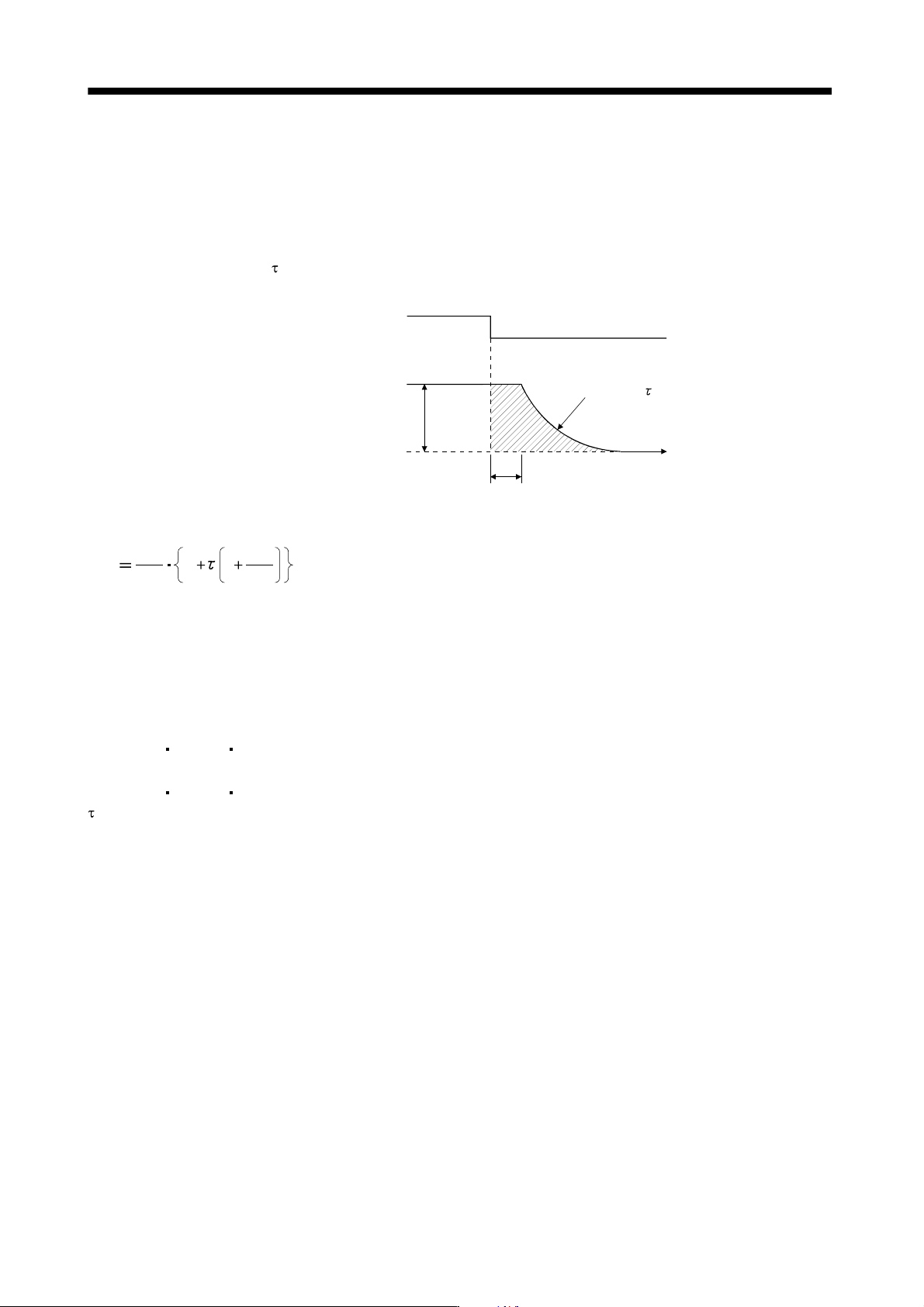
Fig. 13.2 shows the pattern in which the servo motor comes to a stop when the dynamic brake is
operated. Use Equation 13.1 to calculate an approximate coasting distance to a stop. The dynamic
brake time constant
varies with the servo motor and machine operation speeds. (Refer to (b). Please
contact us for the servo motor not indicated.)
te
Forced stop (EM1)
Machine speed
Time constant
Time
OFF
ON
V
0
Fig 13.2 Dynamic Brake Operation Diagram
60
L
max
Vo
t
e
1
JM
JL
·················································································································· (13.1)
L
max : Maximum coasting distance
·········································································································· [mm]
V
0
: Machine rapid feed rate ······························································································
[mm/min][in/min]
J
M
: Servo motor inertial moment ······················································································
[kg
cm
2
][oz in
2
]
J
L
: Load inertia moment converted into equivalent value on servo motor shaft ··············
[kg
cm
2
][oz in
2
]
: Brake time constant
·························································································································· [s]
t
e : Delay time of control section
············································································································ [s]
For 7kW or less servo, there is internal relay delay time of about 30ms. For 11k to 22kW servo, there
is delay time of about 100ms caused by a delay of the external relay and a delay of the magnetic
contactor built in the external dynamic brake.
13 - 70
13. SERVO AMPLIFIERS WITH A LARGE CAPACITY
(
30k TO 55kW
)
(b) Dynamic brake time constant
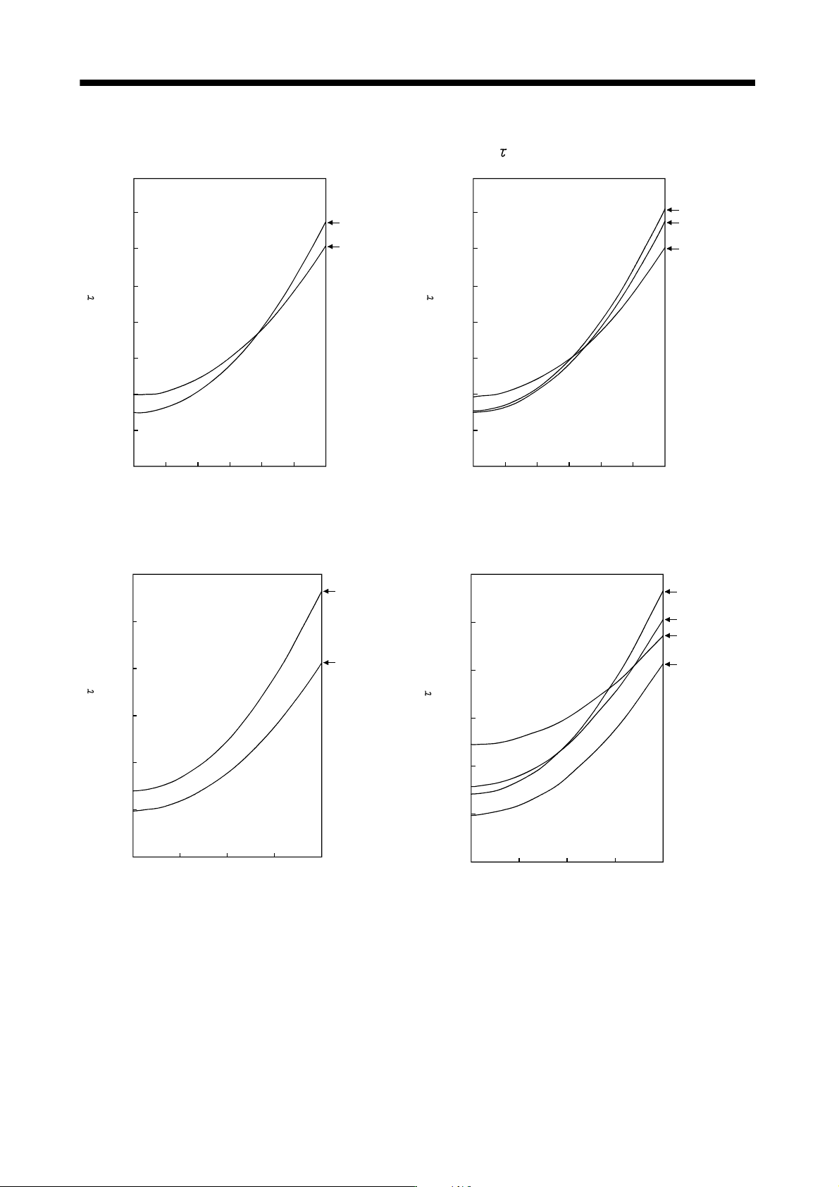
The following shows necessary dynamic brake time constant
for the equations (13.1).
40
35
30
25
20
15
10
5
0
200 600 100001200
Speed [r/min]
HA-LP30K1
HA-LP37K1
400 800
Time constant [ms]
40
35
30
25
20
15
10
5
0
200 600 100001200
Speed [r/min]
400 800
Time constant [ms]
HA-LP30K14
HA-LP37K14
HA-LP25K14
HA-LP1000r/min series
60
50
40
30
20
10
0
1000 150002000
HA-LP30K1M
500
HA-LP37K1M
Speed [r/min]
Time constant [ms]
60
50
40
30
20
10
0
1000 150002000
HA-LP30K1M4
500
HA-LP37K1M4
HA-LP45K1M4
HA-LP50K1M4
Speed [r/min]
Time constant [ms]
HA-LP1500r/min series