sh030051g.pdf - 第32页
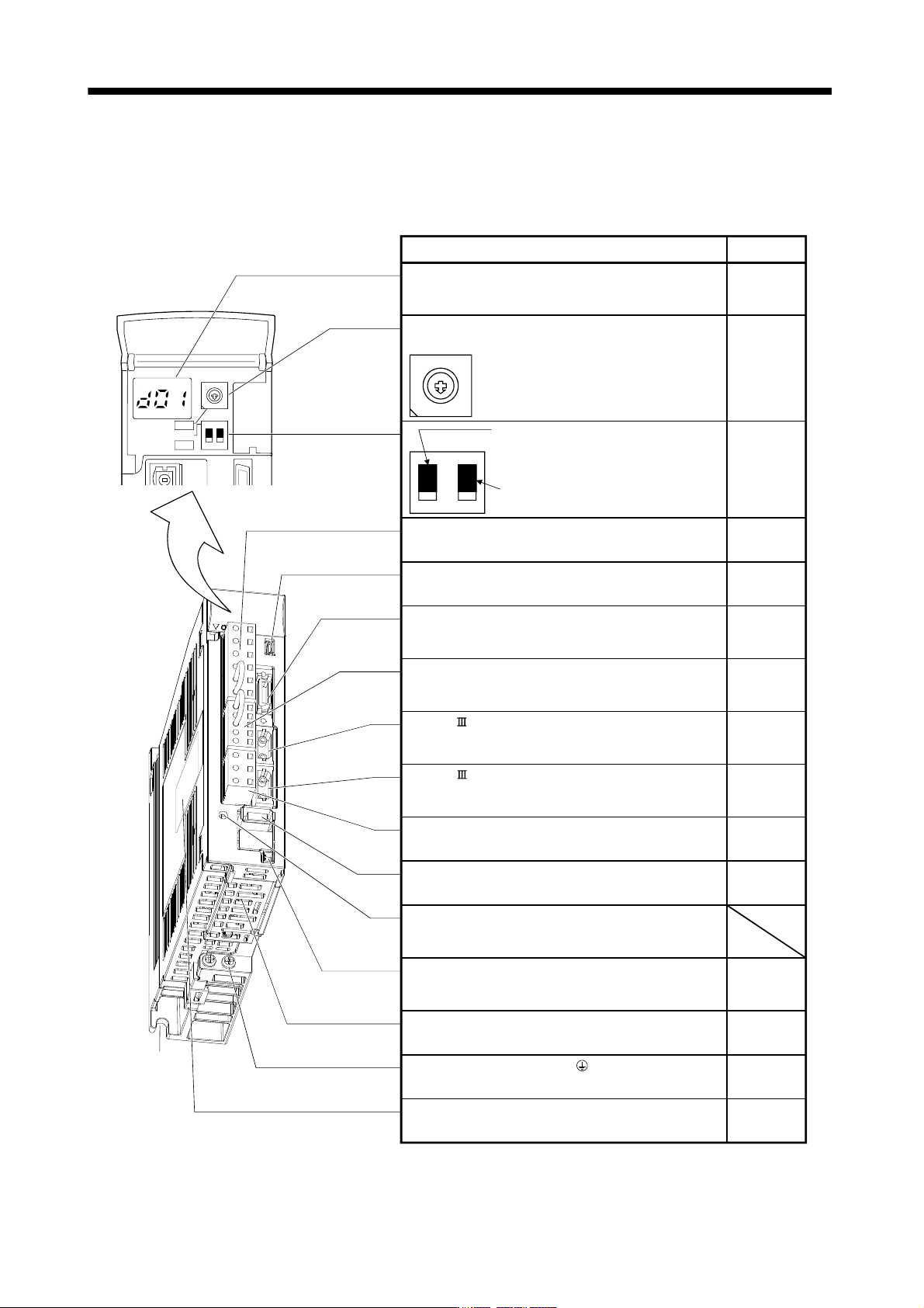
1 - 11 1. FUNCTIONS AND CONFIGURATIO N 1.7 Structure 1.7.1 Parts identification (1) MR-J3-100B or less 7 9 6 8 5 4 3 2 1 0 F E D C B A ON 4F 12 SW1 SW2 Fixed part (2 pl aces ) Used t o set t he axis No. of servo am plifi…
1 - 10
1. FUNCTIONS AND CONFIGURATION
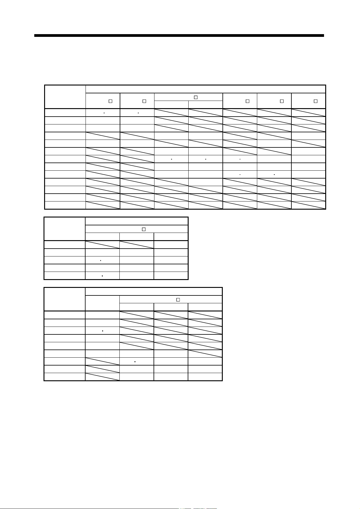
1.6 Combination with servo motor
The following table lists combinations of servo amplifiers and servo motors. The same combinations apply to
the models with an electromagnetic brake and the models with a reduction gear.
Servo amplifier
Servo motors
HF-MP HF-KP
HF-SP
HC-RP
HC-UP HC-LP
1000r/min 2000r/min
MR-J3-10B (1) 053 13 053 13
MR-J3-20B (1) 23 23
MR-J3-40B (1) 43 43
MR-J3-60B 51 52 52
MR-J3-70B 73 73 72
MR-J3-100B 81 102 102
MR-J3-200B 121 201 152 202 103
153
152 152
MR-J3-350B 301 352 203 202 202
MR-J3-500B 421 502 353
503
352
502
302
MR-J3-700B 702
MR-J3-11KB
MR-J3-15KB
MR-J3-22KB
Servo amplifier
Servo motors
HA-LP
1000r/min 1500r/min 2000r/min
MR-J3-500B 502
MR-J3-700B 601 701M 702
MR-J3-11KB 801 12K1 11K1M 11K2
MR-J3-15KB 15K1 15K1M 15K2
MR-J3-22KB 20K1 25K1 22K1M 22K2
Servo amplifier
Servo motors
HF-SP
HA-LP
1000r/min 1500r/min 2000r/min
MR-J3-60B4 524
MR-J3-100B4 1024
MR-J3-200B4 1524 2024
MR-J3-350B4 3524
MR-J3-500B4 5024
MR-J3-700B4 7024 6014 701M4
MR-J3-11KB4 8014 12K14 11K1M4 11K24
MR-J3-15KB4 15K14 15K1M4 15K24
MR-J3-22KB4 20K14 22K1M4 22K24
1 - 11
1. FUNCTIONS AND CONFIGURATION
1.7 Structure
1.7.1 Parts identification
(1) MR-J3-100B or less
7
9
6
8
5
4
3
2
1
0
F
E
D
C
B
A
ON 4F
12
SW1
SW2
Fixed part
(2 places)
Used to set the axis No. of servo amplifier.
Rotary axis setting switch (SW1)
SW2
Test operation select switch (SW2-1)
Used to perform the test operation
mode by using MR Configurator.
Spare (Be sure to set to the "Down"
position).
Detailed
explanation
Section 3.13
Section 3.2
Section 3.4
SW1
Section 3.13
Name/Application
12
Display
The 3-digit, seven-segment LED shows the servo
status and alarm number.
Main circuit power supply connector (CNP1)
Connect the input power supply.
USB communication connector (CN5)
Connect the personal computer.
I/O signal connector (CN3)
Used to connect digital I/O signals.
More over an analog monitor is output.
Control circuit connector (CNP2)
Connect the control circuit power supply/regenerative
option.
SSCNET cable connector (CN1A)
Used to connect the servo system controller or the front
axis servo amplifier.
SSCNET cable connector (CN1B)
Used to connect the rear axis servo amplifier. For the final
axis, puts a cap.
Servo motor power connector (CNP3)
Connect the servo motor.
Encoder connector (CN2)
Used to connect the servo motor encoder.
Charge lamp
Lit to indicate that the main circuit is charged. While
this lamp is lit, do not reconnect the cables.
Battery connector (CN4)
Used to connect the battery for absolute position data
backup.
Battery holder
Contains the battery for absolute position data backup.
Protective earth (PE) terminal ( )
Ground terminal.
Rating plate
7
6
5
4
3
2
1
0
F
E
D
C
B
A
9
8
Chapter 4
Section 3.1
Section 3.3
Section 11.8
Section 3.2
Section 3.4
Section 3.1
Section 3.3
Section 3.2
Section 3.4
Section 3.1
Section 3.3
Section 3.4
Section 11.1
Section 11.9
Chapter 12
Section 12.3
Section 3.1
Section 3.3
Section 1.5
TEST
1 - 12
1. FUNCTIONS AND CONFIGURATION
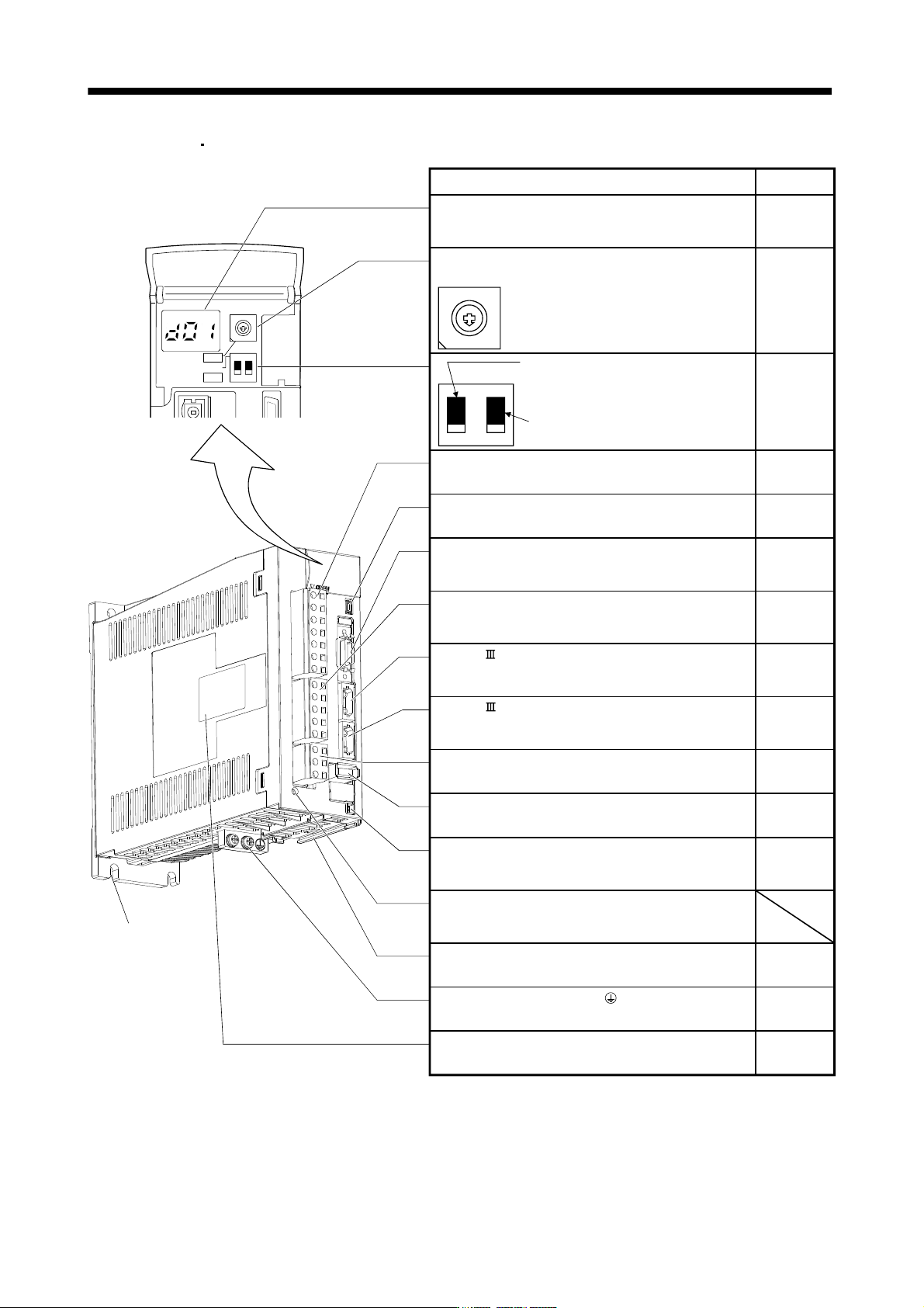
(2) MR-J3-60B4
MR-J3-100B4
Used to set the axis No. of servo amplifier.
Rotary axis setting switch (SW1)
SW2
Test operation select switch (SW2-1)
Used to perform the test operation
mode by using MR Configurator.
Spare (Be sure to set to the "Down"
position).
Detailed
explanation
Section 3.13
Section 3.2
Section 3.4
7
9
6
8
5
4
3
2
1
0
F
E
D
C
B
A
ON 4F
12
SW1
SW1
SW2
TEST
Section 3.13
Name/Application
12
Display
The 3-digit, seven-segment LED shows the servo
status and alarm number.
Main circuit power supply connector (CNP1)
Connect the input power supply.
USB communication connector (CN5)
Connect the personal computer.
I/O signal connector (CN3)
Used to connect digital I/O signals.
More over an analog monitor is output.
Control circuit connector (CNP2)
Connect the control circuit power supply/regenerative
option.
SSCNET cable connector (CN1A)
Used to connect the servo system controller or the front
axis servo amplifier.
SSCNET cable connector (CN1B)
Used to connect the rear axis servo amplifier. For the final
axis, puts a cap.
Servo motor power connector (CNP3)
Connect the servo motor.
Encoder connector (CN2)
Used to connect the servo motor encoder.
Charge lamp
Lit to indicate that the main circuit is charged. While
this lamp is lit, do not reconnect the cables.
Battery connector (CN4)
Used to connect the battery for absolute position data
backup.
Battery holder
Contains the battery for absolute position data backup.
Protective earth (PE) terminal ( )
Ground terminal.
Rating plate
7
6
5
4
3
2
1
0
F
E
D
C
B
A
9
8
Chapter 4
Section 3.1
Section 3.3
Section 11.8
Section 3.2
Section 3.4
Section 3.1
Section 3.3
Section 3.2
Section 3.4
Section 3.1
Section 3.3
Section 3.4
Section 11.1
Section 11.9
Chapter 12
Section 12.3
Section 3.1
Section 3.3
Section 1.5
Fixed part
(3 places)