sh030051g.pdf - 第285页
11 - 80 11. OPTIONS AND AUXILI ARY EQUIPMENT Outline drawing [Unit: mm] Earth plate Clamp section diagram (Note)M4 screw 1 1 3 6 C A 6 22 17.5 35 3 5 L or less 10 3 0 7 2 4 0 0 . 2 2 4 0 . 3 0 B 0 . 3 2- 5 ho le installa…
11 - 79
11. OPTIONS AND AUXILIARY EQUIPMENT
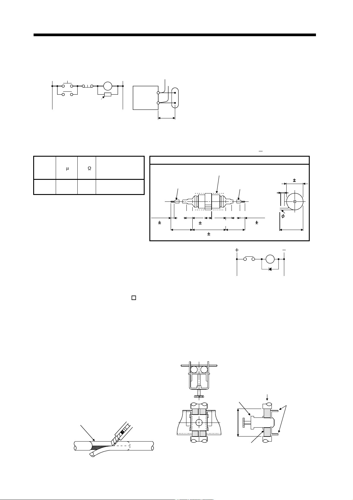
(b) Surge suppressor
The recommended surge suppressor for installation to an AC relay, AC valve or the like near the servo
amplifier is shown below. Use this product or equivalent.
MC
Surge suppressor
Relay
Surge suppresso
r
This distance should be short
(within 20cm).
(Ex.) 972A.2003 50411
(Matsuo Electric Co.,Ltd.
200VAC rating)
Rated
voltage
AC[V]
C [
F] R [ ] Test voltage AC[V]
Outline drawing [Unit: mm]
Blue vinyl cord
Red vinyl cord
Vinyl sheath
200 or more 200 or more
6
31
10 or less
10 or less
15 1
48 1.5
10 310 3
4
18 1.5
200 0.5
50
(1W)
Across
T-C 1000(1 to 5s)
Note that a diode should be installed to a DC relay, DC valve or
the like.
Maximum voltage: Not less than 4 times the drive voltage of the
relay or the like
Maximum current: Not less than twice the drive current of the
relay or the like
Diode
RA
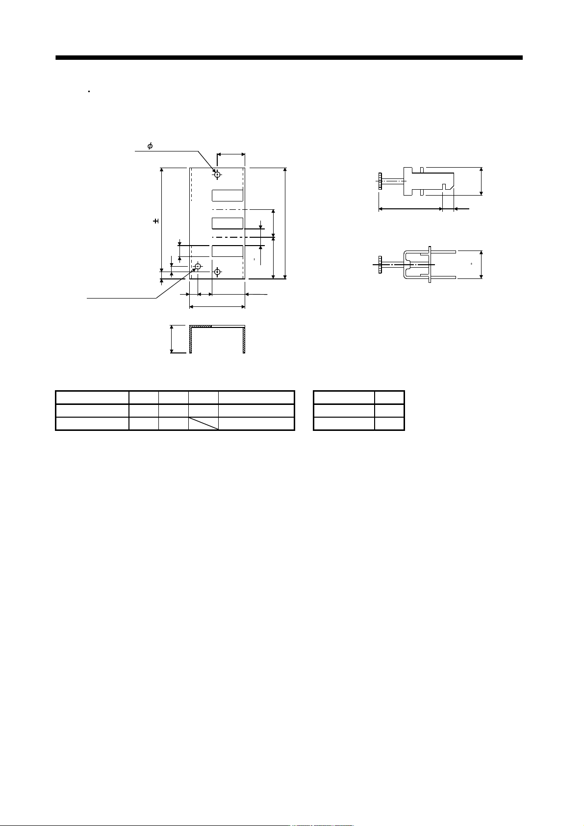
(c) Cable clamp fitting AERSBAN -
SET
Generally, the earth of the shielded cable may only be connected to the connector's SD terminal.
However, the effect can be increased by directly connecting the cable to an earth plate as shown below.
Install the earth plate near the servo amplifier for the encoder cable. Peel part of the cable sheath to
expose the external conductor, and press that part against the earth plate with the cable clamp. If the
cable is thin, clamp several cables in a bunch.
The clamp comes as a set with the earth plate.
[Unit: mm]
Strip the cable sheath of
the clamped area.
cutter
cable
Cable clamp
(A,B)
Cable
Earth plate
External conductor
Clamp section diagram
4
0
11 - 80
11. OPTIONS AND AUXILIARY EQUIPMENT
Outline drawing
[Unit: mm]
Earth plate Clamp section diagram
(Note)M4 screw
1
1
3
6
C
A
6
22
17.5
35
3
5
L or less
10
3
0
7
2
4
0
0
.
2
2
4
0
.
3
0
B
0
.
3
2- 5 hole
installation hole
Note. Screw hole for grounding. Connect it to the earth plate of the control box.
Type A B C Accessory fittings Clamp fitting L
AERSBAN-DSET 100 86 30 clamp A: 2pcs. A 70
AERSBAN-ESET 70 56 clamp B: 1pc. B 45
11 - 81
11. OPTIONS AND AUXILIARY EQUIPMENT
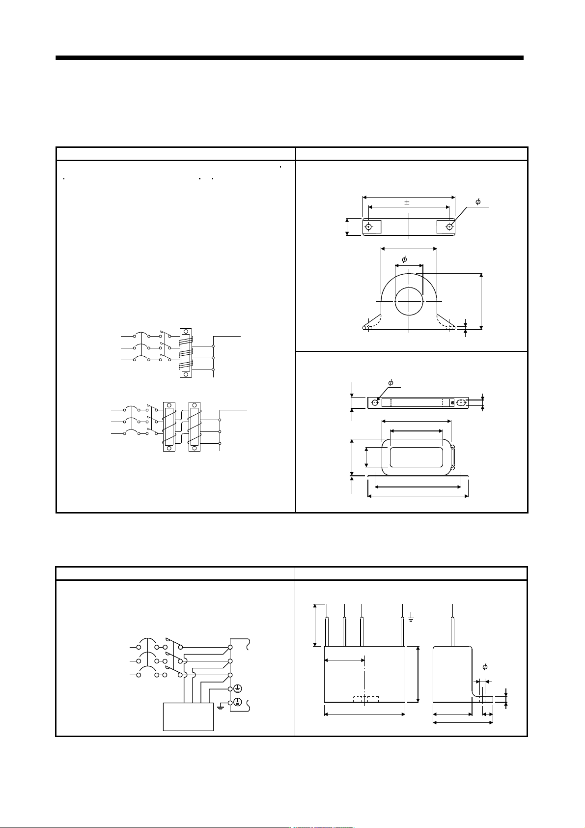
(d) Line noise filter (FR-BSF01, FR-BLF)
This filter is effective in suppressing noises radiated from the power supply side and output side of the
servo amplifier and also in suppressing high-frequency leakage current (zero-phase current) especially
within 0.5MHz to 5MHz band.
Connection diagram Outline drawing [Unit: mm]
Use the line noise filters for wires of the main power supply (L1 L2
L3) and of the motor power supply (U V W). Pass each of the
3-phase wires through the line noise filter an equal number of
times in the same direction. For the main power supply, the effect
of the filter rises as the number of passes increases, but generally
four passes would be appropriate. For the motor power supply,
passes must be four times or less. Do not pass the grounding
(earth) wire through the filter, or the effect of the filter will drop.
Wind the wires by passing through the filter to satisfy the required
number of passes as shown in Example 1. If the wires are too
thick to wind, use two or more filters to have the required number
of passes as shown in Example 2. Place the line noise filters as
close to the servo amplifier as possible for their best performance.
Example 2
Two filters are used
(Total number of turns: 4)
Power
supply
Servo amplifie
r
Line noise
filter
NFB
L
3
L1
L
2
Example 1
(Number of turns: 4)
Power
supply
NFB
L
1
L2
L
3
Servo amplifier
Line noise
filter
MC
MC
FR-BSF01 (for wire size 3.5mm
2
(AWG12) or less))
4
.
5
Approx.110
95 0.5
A
p
p
r
o
x
.
2
2
.
5
A
p
p
r
o
x
.
6
5
Approx.65
33
2- 5
FR-BLF(for wire size 5.5mm
2
(AWG10) or more))
160
180
130
85
8
0
2
.
3
3
5
7
3
1
.
5
7
(e) Radio noise filter (
FR-BIF-(H))
This filter is effective in suppressing noises radiated from the power supply side of the servo amplifier
especially in 10MHz and lower radio frequency bands. The FR-BIF (-H) is designed for the input only.
Connection diagram Outline drawing (Unit: mm)
Make the connection cables as short as possible.
Grounding is always required.
When using the FR-BIF with a single-phase power
supply, always insulate the wires that are not used
for wiring.
Servo amplifier
NFB
L3
L
2
L1
MC
Power
supply
Radio noise
filter FR-BIF
-(H)
200V class: FR-BIF
400V class: FR-BIF-H
Leakage current: 4mA
29
58
4
2
4
Red BlueWhite Green
44
29
7
hole
A
b
o
u
t
3
0
0
5