sh030051g.pdf - 第287页
11 - 82 11. OPTIONS AND AUXILI ARY EQUIPMENT (f) Varistors for input power supply (Recommended) Varistors are effective to prevent exogenous noise and lightning surge from enterin g the servo amplifier. When using a vari…
11 - 81
11. OPTIONS AND AUXILIARY EQUIPMENT
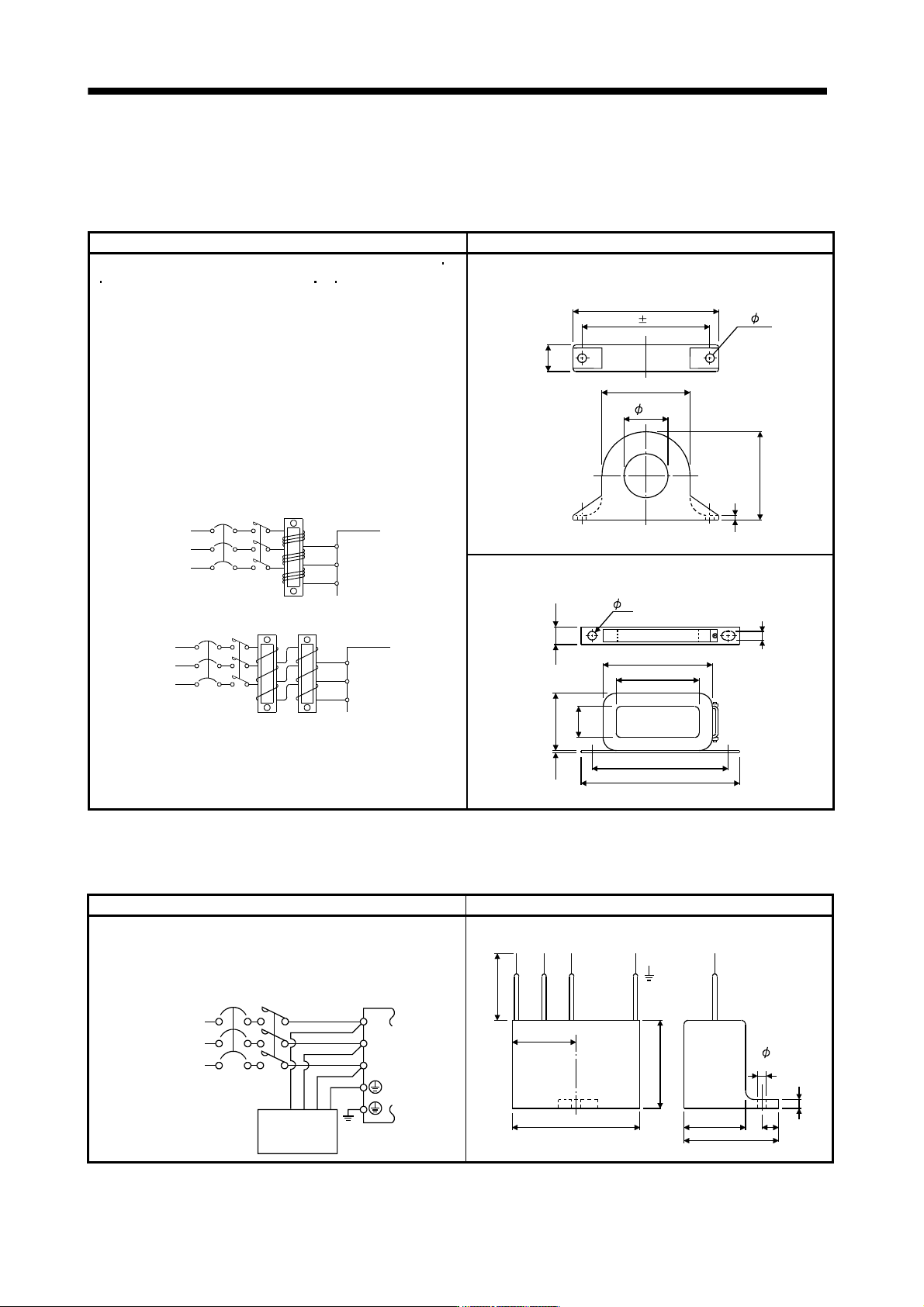
(d) Line noise filter (FR-BSF01, FR-BLF)
This filter is effective in suppressing noises radiated from the power supply side and output side of the
servo amplifier and also in suppressing high-frequency leakage current (zero-phase current) especially
within 0.5MHz to 5MHz band.
Connection diagram Outline drawing [Unit: mm]
Use the line noise filters for wires of the main power supply (L1 L2
L3) and of the motor power supply (U V W). Pass each of the
3-phase wires through the line noise filter an equal number of
times in the same direction. For the main power supply, the effect
of the filter rises as the number of passes increases, but generally
four passes would be appropriate. For the motor power supply,
passes must be four times or less. Do not pass the grounding
(earth) wire through the filter, or the effect of the filter will drop.
Wind the wires by passing through the filter to satisfy the required
number of passes as shown in Example 1. If the wires are too
thick to wind, use two or more filters to have the required number
of passes as shown in Example 2. Place the line noise filters as
close to the servo amplifier as possible for their best performance.
Example 2
Two filters are used
(Total number of turns: 4)
Power
supply
Servo amplifie
r
Line noise
filter
NFB
L
3
L1
L
2
Example 1
(Number of turns: 4)
Power
supply
NFB
L
1
L2
L
3
Servo amplifier
Line noise
filter
MC
MC
FR-BSF01 (for wire size 3.5mm
2
(AWG12) or less))
4
.
5
Approx.110
95 0.5
A
p
p
r
o
x
.
2
2
.
5
A
p
p
r
o
x
.
6
5
Approx.65
33
2- 5
FR-BLF(for wire size 5.5mm
2
(AWG10) or more))
160
180
130
85
8
0
2
.
3
3
5
7
3
1
.
5
7
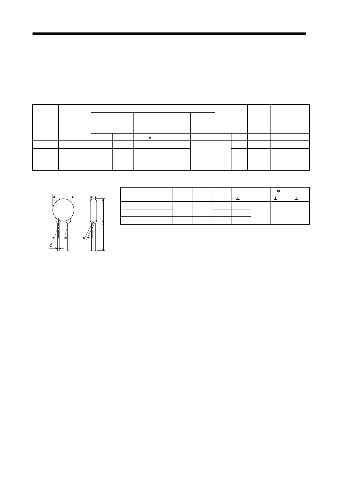
(e) Radio noise filter (
FR-BIF-(H))
This filter is effective in suppressing noises radiated from the power supply side of the servo amplifier
especially in 10MHz and lower radio frequency bands. The FR-BIF (-H) is designed for the input only.
Connection diagram Outline drawing (Unit: mm)
Make the connection cables as short as possible.
Grounding is always required.
When using the FR-BIF with a single-phase power
supply, always insulate the wires that are not used
for wiring.
Servo amplifier
NFB
L3
L
2
L1
MC
Power
supply
Radio noise
filter FR-BIF
-(H)
200V class: FR-BIF
400V class: FR-BIF-H
Leakage current: 4mA
29
58
4
2
4
Red BlueWhite Green
44
29
7
hole
A
b
o
u
t
3
0
0
5
11 - 82
11. OPTIONS AND AUXILIARY EQUIPMENT
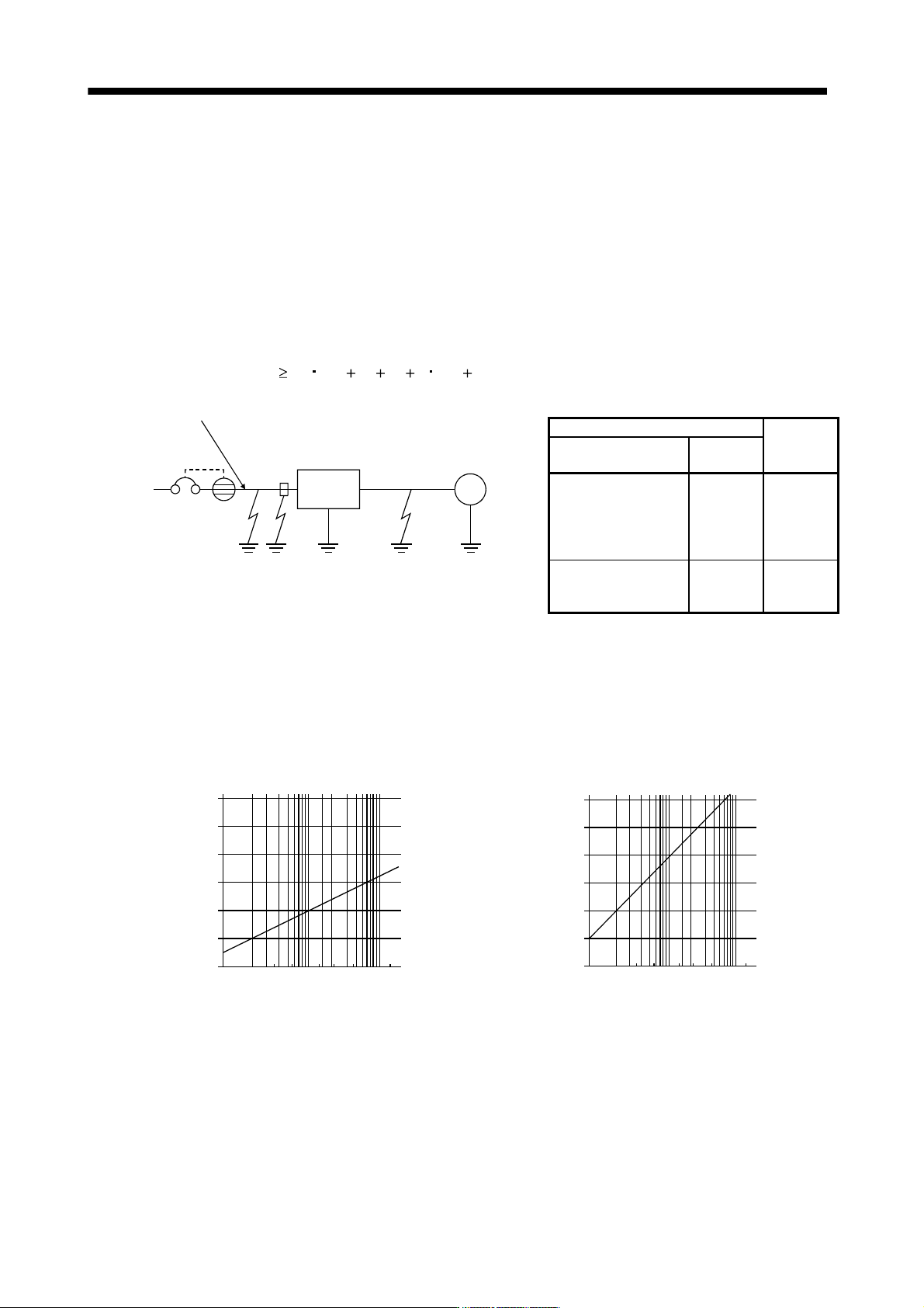
(f) Varistors for input power supply (Recommended)
Varistors are effective to prevent exogenous noise and lightning surge from entering the servo amplifier.
When using a varistor, connect it between each phase of the input power supply of the equipment. For
varistors, the TND20V-431K, TND20V-471K and TND20V-102K, manufactured by NIPPON CHEMI-
CON, are recommended. For detailed specification and usage of the varistors, refer to the manufacturer
catalog.
Power
supply
voltage
Varistor
Maximum rating
Maximum limit
voltage
Static
capacity
(reference
value)
Varistor voltage
rating (range)
V1mA
Permissible circuit
voltage
Surge current
immunity
Energy
immunity
Rated
pulse
power
AC[Vrms] DC[V] 8/20 s[A] 2ms[J] [W] [A] [V] [pF] [V]
100V class TND20V-431K 275 350 10000/1 time 195
1.0 100
710 1300 430(387 to 473)
200V class TND20V-471K 300 385 7000/2 time 215 775 1200 470(423 to 517)
400V class TND20V-102K 625 825
7500/1 time
6500/2 time
400 1650 500 1000(900 to 1100)
[Unit: mm]
d
W E
H
D
L
T
Model
D
Max.
H
Max.
T
Max.
E
1.0
(Note)L
min.
d
0.05
W
1.0
TND20V-431K
21.5 24.5
6.4 3.3
TND20V-471K 6.6 3.5 20 0.8 10.0
TND20V-102K 22.5 25.5 9.5 6.4
Note. For special purpose items for lead length (L), contact the manufacturer.
11 - 83
11. OPTIONS AND AUXILIARY EQUIPMENT
11.18 Leakage current breaker
(1) Selection method
High-frequency chopper currents controlled by pulse width modulation flow in the AC servo circuits.
Leakage currents containing harmonic contents are larger than those of the motor which is run with a
commercial power supply.
Select a leakage current breaker according to the following formula, and ground the servo amplifier, servo
motor, etc. securely.
Make the input and output cables as short as possible, and also make the grounding cable as long as
possible (about 30cm) to minimize leakage currents.
Rated sensitivity current
10 {Ig1 Ign Iga K (Ig2 Igm)} [mA] (11.1)
M
Servo
amplifier
Noise
filter
NV
I
g
1I
g
nI
g
aI
g
2I
g
m
Cable
Cable
K: Constant considering the harmonic contents
Leakage current breaker
K
Type
Mitsubishi
products
Models provided with
harmonic and surge
reduction techniques
NV-SP
NV-SW
NV-CP
NV-CW
NV-L
1
General models
BV-C1
NFB
NV-L
3
Ig1: Leakage current on the electric channel from the leakage current breaker to the input terminals of the
servo amplifier (Found from Fig. 11.3.)
Ig2: Leakage current on the electric channel from the output terminals of the servo amplifier to the
servo motor (Found from Fig. 11.3.)
Ign: Leakage current when a filter is connected to the input side (4.4mA per one FR-BIF(-H))
Iga: Leakage current of the servo amplifier (Found from Table 11.5.)
Igm: Leakage current of the servo motor (Found from Table 11.4.)
120
100
80
60
40
20
0
23.5
5.5
814223880150
30 60 100
Cable size[mm
2
]
[mA]
L
e
a
k
a
g
e
c
u
r
r
e
n
t
120
100
80
60
40
20
0
2
3.5
5.5
8
14
22
38
80
150
30
60
100
Cable size[mm
2
]
[mA]
L
e
a
k
a
g
e
c
u
r
r
e
n
t
a. 200V class
b. 400V class
Fig. 11.3 Leakage current example (lg1, lg2) for CV cable run in metal conduit