sh030051g.pdf - 第278页
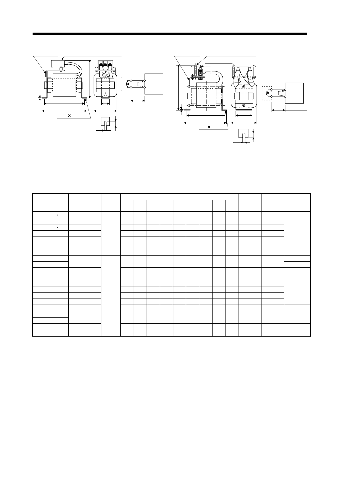
11 - 73 11. OPTIONS AND AUXILI ARY EQUIPMENT Rating plate L H B or less E A or less Terminal box - screw s ize G Mounting leg D F C or less Servo amplifier P 1 P 2 (Not e 2) FR-BEL-(H) 2-F L notch 5m or le ss Servo ampli…
11 - 72
11. OPTIONS AND AUXILIARY EQUIPMENT
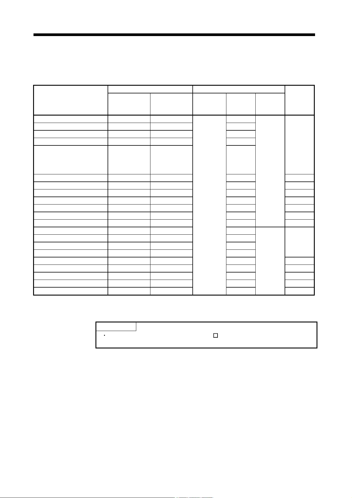
11.12 No-fuse breakers, fuses, magnetic contactors
Always use one no-fuse breaker and one magnetic contactor with one servo amplifier. When using a fuse
instead of the no-fuse breaker, use the one having the specifications given in this section.
Servo amplifier
No-fuse breaker Fuse
Magnetic
contactor
Not using power
factor improving
reactor
Using power factor
improving reactor
(Note) Class Current [A]
Voltage
AC [V]
MR-J3-10B (1) 30A frame 5A 30A frame 5A 10
250
S-N10
MR-J3-20B 30A frame 5A 30A frame 5A 10
MR-J3-20B1 30A frame 10A 30A frame 10A 15
MR-J3-40B 30A frame 10A 30A frame 5A 15
MR-J3-60B
MR-J3-70B
MR-J3-100B
MR-J3-40B1
30A frame 15A 30A frame 10A 20
MR-J3-200B 30A frame 20A 30A frame 15A 40 S-N18
MR-J3-350B 30A frame 30A 30A frame 30A 70 S-N20
MR-J3-500B 50A frame 50A 50A frame 40A 125 S-N35
MR-J3-700B 100A frame 75A 50A frame 50A
T
150 S-N50
MR-J3-11KB 100A frame 100A 100A frame 75A 200 S-N65
MR-J3-15KB 225A frame 125A 100A frame 100A 250 S-N95
MR-J3-22KB 225A frame 175A 225A frame 150A 350 S-N125
MR-J3-60B4 30A frame 5A 30A frame 5A 10
600
MR-J3-100B4 30A frame 10A 30A frame 10A 15
S-N10
MR-J3-200B4 30A frame 15A 30A frame 15A 25
MR-J3-350B4 30A frame 20A 30A frame 20A 35
MR-J3-500B4 30A frame 30A 30A frame 30A 50 S-N18
MR-J3-700B4 50A frame 40A 50A frame 30A 65 S-N20
MR-J3-11KB4 60A frame 60A 50A frame 50A 100 S-N25
MR-J3-15KB4 100A frame 75A 60A frame 60A 150 S-N35
MR-J3-22KB4 225A frame 125A 100A frame 100A 175 S-N65
Note. When not using the servo amplifier as a UL/C-UL Standard compliant product, K5 class fuse can be used.
11.13 Power factor improving DC reactor
POINT
For the 100V power supply type (MR-J3- B1), the power factor improving DC
reactor cannot be used.
The power factor improving DC reactor increases the form factor of the servo amplifier's input current to
improve the power factor. It can decrease the power supply capacity. As compared to the power factor
improving AC reactor (FR-BAL), it can decrease the loss. The input power factor is improved to about 95%.
It is also effective to reduce the input side harmonics.
When connecting the power factor improving DC reactor to the servo amplifier, always disconnect P
1
and P
2
(For 11kW or more, disconnect P
1
and P). If it remains connected, the effect of the power factor improving DC
reactor is not produced.
When used, the power factor improving DC reactor generates heat. To release heat, therefore, leave a 10cm or
more clearance at each of the top and bottom, and a 5cm or more clearance on each side.
11 - 73
11. OPTIONS AND AUXILIARY EQUIPMENT
Rating plate
L
H
B or less
E
A or less
Terminal box - screw size G
Mounting leg
D
F
C or less
Servo amplifier
P
1
P2
(Note 2)
FR-BEL-(H)
2-F L notch
5m or less
Servo amplifier
P
1
P
2
(Note 2)
FR-BEL-(H)
(Note 3)
B or lessA or less
Mounting leg
Rating plate
2-F L notch
Screw size G
(Note 1)Terminal cover
E
D
H
F
L
C or less
5m or less
Fig. 11.1 Fig. 11.2
Note 1. Since the terminal cover is supplied, attach it after connecting a wire.
2. When using DC reactor, disconnect P
1 and P2.
3. When over 11kW, "P
2" becomes "P", respectively.
Servo amplifier
Power factor
improving DC
reactor
Outline
drawing
Dimensions [mm]
Mounting
screw size
Mass
[kg(lb)]
Wire
[mm
2
] (Note)
A B C D E F L G H
MR-J3-10B 20B FR-BEL-0.4K 110 50 94 1.6 95 6 12 M3.5 25 M5 0.5(1.10)
MR-J3-40B FR-BEL-0.75K 120 53 102 1.6 105 6 12 M4 25 M5 0.7(1.54)
MR-J3-60B 70B FR-BEL-1.5K 130 65 110 1.6 115 6 12 M4 30 M5 1.1(2.43) 2(AWG14)
MR-J3-100B FR-BEL-2.2K Fug. 11.1 130 65 110 1.6 115 6 12 M4 30 M5 1.2(2.65)
MR-J3-200B FR-BEL-3.7K 150 75 102 2.0 135 6 12 M4 40 M5 1.7(3.75)
MR-J3-350B FR-BEL-7.5K 150 75 126 2.0 135 6 12 M5 40 M5 2.3(5.07) 3.5(AWG12)
MR-J3-500B FR-BEL-11K 170 93 132 2.3 155 6 14 M5 50 M5 3.1(6.83) 5.5(AWG10)
MR-J3-700B
FR-BEL-15K
170 93 170 2.3 155 6 14 M8 56 M5 3.8(8.38)
8(AWG8)
MR-J3-11KB
Fig. 11.2
22(AWG4)
MR-J3-15KB FR-BEL-22K 185 119 182 2.6 165 7 15 M8 70 M6 5.4(11.91) 30(AWG2)
MR-J3-22KB FR-BEL-30K 185 119 201 2.6 165 7 15 M8 70 M6 6.7(14.77) 60(AWG2/0)
MR-J3-60B4 FR-BEL-H1.5K 130 63 89 1.6 115 6 12 M3.5 32 M5 0.9(1.98)
MR-J3-100B4 FR-BEL-H2.2K 130 63 101 1.6 115 6 12 M3.5 32 M5 1.1(2.43)
2(AWG14)
MR-J3-200B4 FR-BEL-H3.7K Fig. 11.1 150 75 102 2 135 6 12 M4 40 M5 1.7(3.75)
MR-J3-350B4 FR-BEL-H7.5K 150 75 124 2 135 6 12 M4 40 M5 2.3(5.07)
MR-J3-500B4 FR-BEL-H11K 170 93 132 2.3 155 6 14 M5 50 M5 3.1(6.83) 5.5(AWG10)
MR-J3-700B4
FR-BEL-H15K
170 93 160 2.3 155 6 14 M6 56 M5 3.7(8.16) 8(AWG8)
MR-J3-11KB4
Fig. 11.2
MR-J3-15KB4 FR-BEL-H22K 185 119 171 2.6 165 7 15 M6 70 M6 5.0(11.02)
22(AWG4)
MR-J3-22KB4 FR-BEL-H30K 185 119 189 2.6 165 7 15 M6 70 M6 6.7(14.77)
Note. Selection condition of wire size is as follows.
Wire type: 600V Polyvinyl chloride insulated wire (IV wire)
Construction condition: One wire is constructed in the air
11 - 74
11. OPTIONS AND AUXILIARY EQUIPMENT
11.14 Power factor improving AC reactors
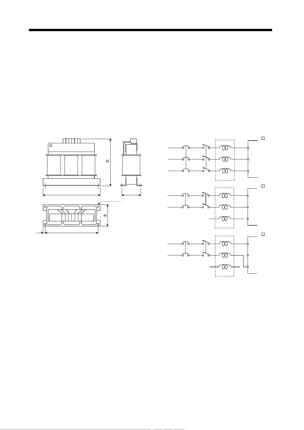
The power factor improving AC reactors improve the phase factor by increasing the form factor of servo
amplifier's input current.
It can reduce the power capacity.
The input power factor is improved to be about 90%. For use with a 1-phase power supply, it may be slightly
lower than 90%.
In addition, it reduces the higher harmonic of input side.
When using power factor improving reactors for two servo amplifiers or more, be sure to connect a power factor
improving reactor to each servo amplifier.
If using only one power factor improving reactor, enough improvement effect of phase factor cannot be
obtained unless all servo amplifiers are operated.
Z
3-phase
200 to 230VAC
or
3-phase
380 to 480VAC
NFB
FR-BAL-(H)
Servo amplifie
r
MR-J3- B(4)
R
S
T
X
Y
Z
L
1
L
2
L
3
MC
1-phase
200v to 230VAC
NFB
FR-BAL
Servo amplifier
MR-J3- B
R
S
T
X
Y
Z
L
1
L
2
L
3
MC
W
W1C
RXSYTZ
H 5
D1
Installation screw
D 5
[Unit : mm]
(Note)
1-phase
100 to120VAC
NFB
FR-BAL
Servo amplifier
MR-J3- B1
R
S
T
X
Y
L
1
Blank
MC
L
2
Note. For the 1-phase 200V to 230V power supply, Connect the power
supply to L
1
, L
2
and leave L
3
open.