sh030051g.pdf - 第266页
11 - 61 11. OPTIONS AND AUXILI ARY EQUIPMENT 11.7 Junction terminal block PS7DW-20 V14B-F (recommended) (1) How to use the junction terminal block Always use the junction terminal block (PS7W- 20V14B-F(YOSHI DA ELECTRIC …
11 - 60
11. OPTIONS AND AUXILIARY EQUIPMENT
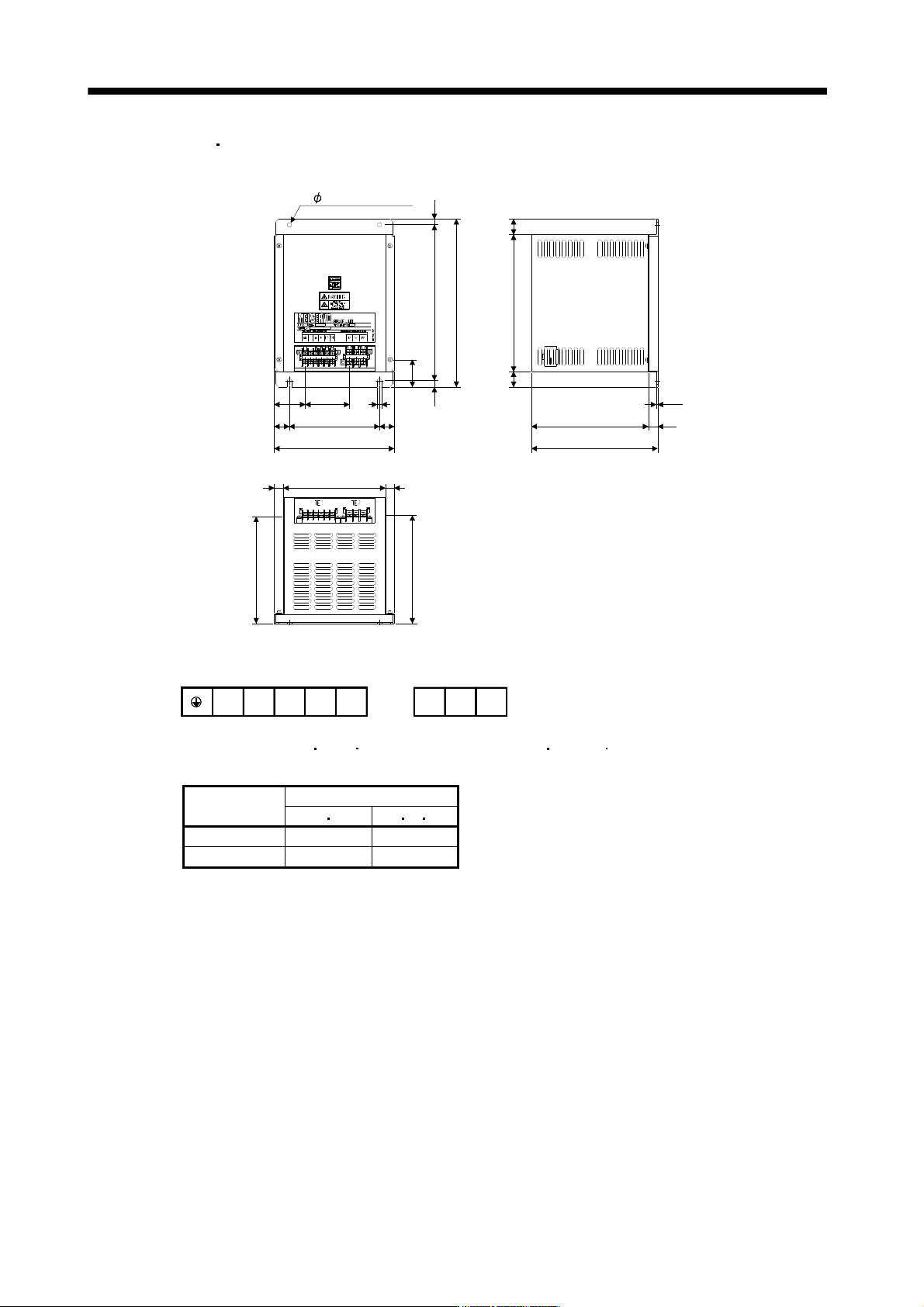
(b) DBU-11K-4
DBU-22K-4
[Unit: mm]
15
51
25
15
73.75 7
25150
10
200
170
178.5
179.5
15
260
280
43
10
2- 7mounting hole
195
228
2626
210
2.3
Mass: 6.7[kg]
a
TE1
Tightening torque: 0.8[N m](7[lb in])
Screw: M3.5
b 13 14
Terminal block
WVU
Tightening torque: 1.2[N m](10.6[lb in])
Screw: M4
TE2
Dynamic brake
Wire [mm
2
] (Note)
a b U V W
DBU-11K 2 5.5
DBU-15K, 22K 2 5.5
Note. Selection condition of wire size is as follows.
Wire type: 600V Polyvinyl chloride insulated wire (IV wire)
Construction condition: One wire is constructed in the air
11 - 61
11. OPTIONS AND AUXILIARY EQUIPMENT
11.7 Junction terminal block PS7DW-20V14B-F (recommended)
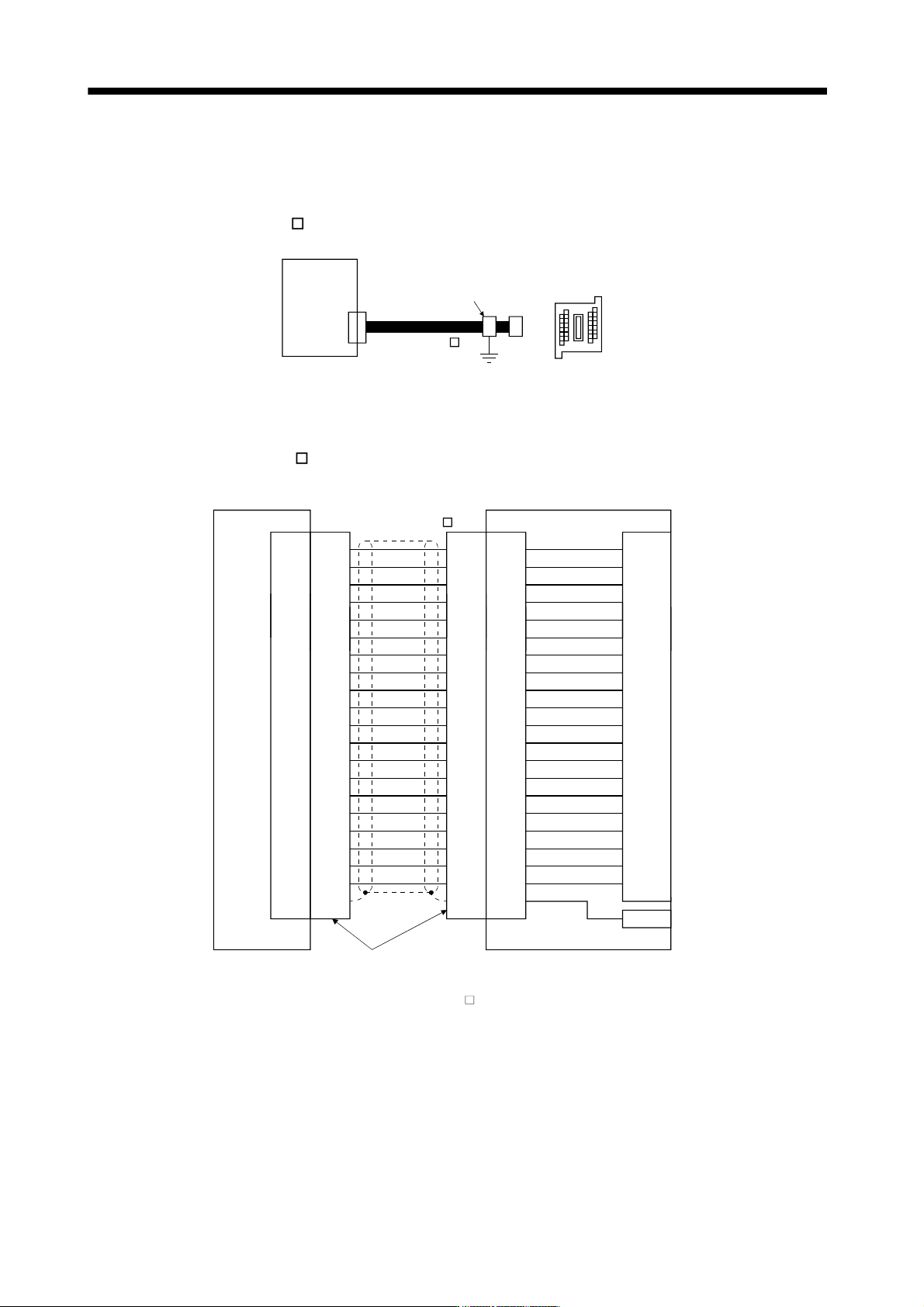
(1) How to use the junction terminal block
Always use the junction terminal block (PS7W-20V14B-F(YOSHIDA ELECTRIC INDUSTRY)) with the
option cable (MR-J2HBUS
M) as a set. A connection example is shown below.
Servo amplifier
Cable clamp
(AERSBAN-ESET)
Junction terminal block
PS7DW-20V14B-F
CN3
MR-J2HBUS M
Ground the option cable on the junction terminal block side with the cable clamp fitting (AERSBAN-ESET).
For the use of the cable clamp fitting, refer to section 11.14, (2)(c).
(2) Connection of MR-J2HBUS
M cable and junction terminal block
LG
DI1
1
2
DOC
MO1
3
4
LZ 8
LB 7
9
SD Shell
INP
5
6
10DICO
DICO
LA
LG
DI2
11
12
MBR
MO2
13
14
LZR 18
LBR 17
19DI3
15
16
20EM1
AMR
LAR
Shell Shell Shell
1
2
3
4
8
7
9
5
6
10
11
12
13
14
18
17
19
15
16
20
1
2
3
4
8
7
9
5
6
10
11
12
13
14
18
17
19
15
16
20
1
2
3
4
8
7
9
5
6
10
11
12
13
14
18
17
19
15
16
20
LG
DI1
DOC
MO1
LZ
LB
SD
INP
DICO
DICO
LA
LG
DI2
MBR
MO2
LZR
LBR
DI3
EM1
AMR
LAR
E
Servo amplifier
CN3
Junction terminal block
PS7W-20V14B-F
Connector: 10120-6000EL (3M)
Shell kit: 10320-3210-000 (3M)
CN
Terminal block
1
2
3
4
8
7
9
5
6
10
11
12
13
14
18
17
19
15
16
20
(Note)MR-J2HBUS M
Note. Symbol indicating cable length is put in .
05: 0.5m
1: 1m
5: 5m
11 - 62
11. OPTIONS AND AUXILIARY EQUIPMENT
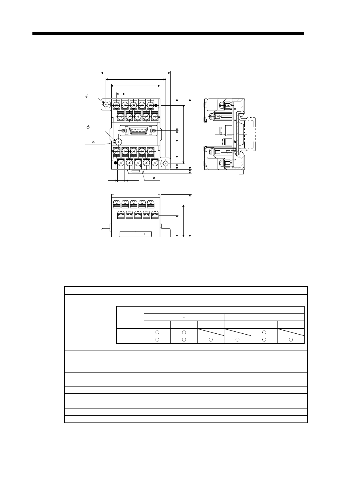
(3) Outline drawings of junction terminal block
[Unit : mm]
TB.E
( 6)
36.5
27.8
18.8
7.62
44.11
54
63
4.5
4.5
5
4
60
50
9.3
27
M3 5L
M3 6L
1.42
6.2
11.8 MR Configurator
The MR Configurator (MRZJW3-SETUP221E) uses the communication function of the servo amplifier to
perform parameter setting changes, graph display, test operation, etc. on a personal computer.
(1) Specifications
Item Description
Compatibility with a
servo amplifier
The following table shows MR Configurator software version for each servo amplifier.
Version
Compatible servo amplifier (Drive unit)
100V class 200V class 400V class
7kW or less 11k to 22kW 30k to 37kW 7kW or less 11k to 22kW 30k to 55kW
B1
C0 or later
Monitor
Display, high speed monitor, trend graph
Minimum resolution changes with the processing speed of the personal computer.
Alarm Display, history, amplifier data
Diagnostic
Digital I/O, no motor rotation, total power-on time, amplifier version info, motor information,
tuning data, absolute encoder data, Axis name setting.
Parameters Parameter list, turning, change list, detailed information
Test operation Jog operation, positioning operation, Do forced output, program operation.
Advanced function Machine analyzer, gain search, machine simulation.
File operation Data read, save, delete, print
Others Automatic demo, help display