sh030051g.pdf - 第199页
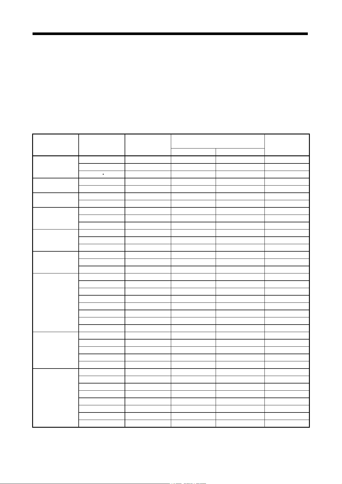
10 - 4 10. CHARACTERISTIC S Servo amplifier Servo motor (Note 1) Power supply capacity[kVA] (Note 2) Servo amplifier-generated heat[W] Area required for heat dissipation At rated torque With servo off [m 2 ] MR-J3-700B (…
10 - 3
10. CHARACTERISTICS
10.2 Power supply equipment capacity and generated loss
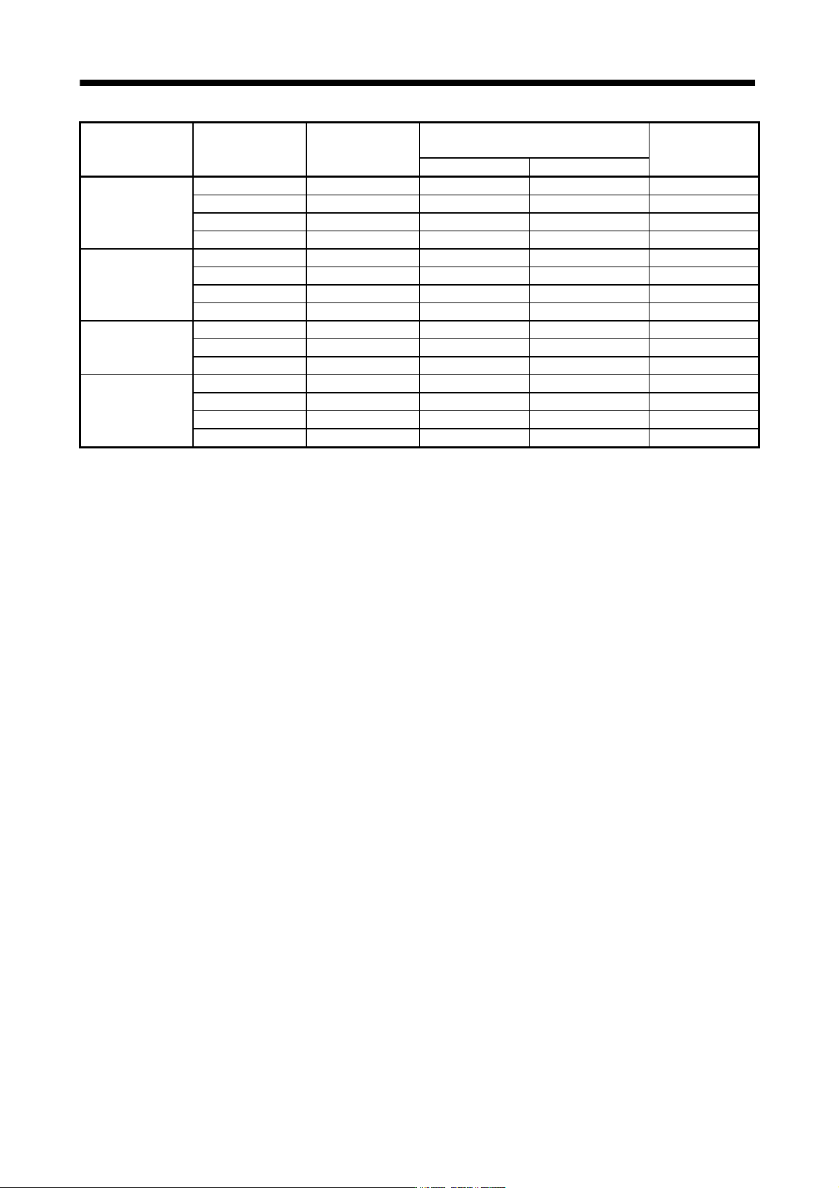
(1) Amount of heat generated by the servo amplifier
Table 10.1 indicates servo amplifiers' power supply capacities and losses generated under rated load. For
thermal design of an enclosure, use the values in Table 10.1 in consideration for the worst operating
conditions. The actual amount of generated heat will be intermediate between values at rated torque and
servo off according to the duty used during operation. When the servo motor is run at less than the
maximum speed, the power supply capacity will be smaller than the value in the table, but the servo
amplifier's generated heat will not change.
Table 10.1 Power supply capacity and generated heat per servo amplifier at rated output
Servo amplifier Servo motor
(Note 1)
Power supply
capacity[kVA]
(Note 2)
Servo amplifier-generated heat[W]
Area required for
heat dissipation
At rated torque With servo off [m
2
]
MR-J3-10B (1)
HF-MP053 0.3 25 15 0.5
HF-MP13 0.3 25 15 0.5
HF-KP053 13 0.3 25 15 0.5
MR-J3-20B (1)
HF-MP23 0.5 25 15 0.5
HF-KP23 0.5 25 15 0.5
MR-J3-40B (1)
HF-MP43 0.9 35 15 0.7
HF-KP43 0.9 35 15 0.7
MR-J3-60B (4)
HF-SP52 (4) 1.0 40 15 0.8
HF-SP51 1.0 40 15 0.8
HC-LP52 1.0 40 15 0.8
MR-J3-70B
HF-MP73 1.3 50 15 1.0
HF-KP73 1.3 50 15 1.0
HC-UP72 1.3 50 15 1.0
MR-J3-100B (4)
HF-SP102 (4) 1.7 50 15 1.0
HF-SP81 1.5 50 15 1.0
HC-LP102 1.7 50 15 1.0
MR-J3-200B (4)
HF-SP152 (4) 2.5 90 20 1.8
HF-SP202 (4) 3.5 90 20 1.8
HF-SP121 2.1 90 20 1.8
HF-SP201 3.5 90 20 1.8
HC-RP103 1.8 50 15 1.0
HC-RP153 2.5 90 20 1.8
HC-UP152 2.5 90 20 1.8
HC-LP152 2.5 90 20 1.8
MR-J3-350B (4)
HF-SP352 (4) 5.5 130 20 (25) (Note 3) 2.7
HC-RP203 3.5 90 20 1.8
HC-UP202 3.5 90 20 1.8
HC-LP202 3.5 90 20 1.8
HF-SP301 4.8 120 20 2.4
MR-J3-500B (4)
HF-SP502 (4) 7.5 195 25 3.9
HC-RP353 5.5 135 25 2.7
HC-RP503 7.5 195 25 3.9
HC-UP352 5.5 195 25 3.9
HC-UP502 7.5 195 25 3.9
HC-LP302 4.5 120 25 2.4
HA-LP502 7.5 195 25 3.9
HF-SP421 6.7 160 25 3.2
10 - 4
10. CHARACTERISTICS
Servo amplifier Servo motor
(Note 1)
Power supply
capacity[kVA]
(Note 2)
Servo amplifier-generated heat[W]
Area required for
heat dissipation
At rated torque With servo off [m
2
]
MR-J3-700B (4)
HF-SP702 (4) 10.0 300 25 6.0
HA-LP702 10.6 300 25 6.0
HA-LP601 (4) 10.0 260 25 5.2
HA-LP701M (4) 11.0 300 25 6.0
MR-J3-11KB
HC-LP11K2 (4) 16.0 530 45 11.0
HC-LP801 (4) 12.0 390 45 7.8
HC-LP12K1 (4) 18.0 580 45 11.6
HC-LP11K1M (4) 16.0 530 45 11.0
MR-J3-15KB
HC-LP15K2 (4) 22.0 640 45 13.0
HC-LP15K1 (4) 22.0 640 45 13.0
HC-LP15K1M (4) 22.0 640 45 13.0
MR-J3-22KB
HC-LP22K2 (4) 33.0 850 55 17.0
HC-LP20K1 (4) 30.1 775 55 15.5
HC-LP25K1 37.6 970 55 19.4
HC-LP22K1M (4) 33.0 850 55 17.0
Note 1. Note that the power supply capacity will vary according to the power supply impedance. This value is applicable when the
power factor improving reactor is not used.
2. Heat generated during regeneration is not included in the servo amplifier-generated heat. To calculate heat generated by the
regenerative option, refer to section 11.2.
3. For 400V class, the value is within the ( ).
10 - 5
10. CHARACTERISTICS
(2) Heat dissipation area for enclosed servo amplifier
The enclosed control box (hereafter called the control box) which will contain the servo amplifier should be
designed to ensure that its temperature rise is within
10 at the ambient temperature of 40 . (With a 5
(41
) safety margin, the system should operate within a maximum 55 (131 ) limit.) The necessary
enclosure heat dissipation area can be calculated by Equation 10.1.
P
A
KT
............................................................................................................................................. (10.1)
where, A : Heat dissipation area [m
2
]
P : Loss generated in the control box [W]
T : Difference between internal and ambient temperatures [ ]
K : Heat dissipation coefficient [5 to 6]
When calculating the heat dissipation area with Equation 10.1, assume that P is the sum of all losses
generated in the enclosure. Refer to Table 10.1 for heat generated by the servo amplifier. "A" indicates the
effective area for heat dissipation, but if the enclosure is directly installed on an insulated wall, that extra
amount must be added to the enclosure's surface area.
The required heat dissipation area will vary wit the conditions in the enclosure. If convection in the
enclosure is poor and heat builds up, effective heat dissipation will not be possible. Therefore, arrangement
of the equipment in the enclosure and the use of a cooling fan should be considered.
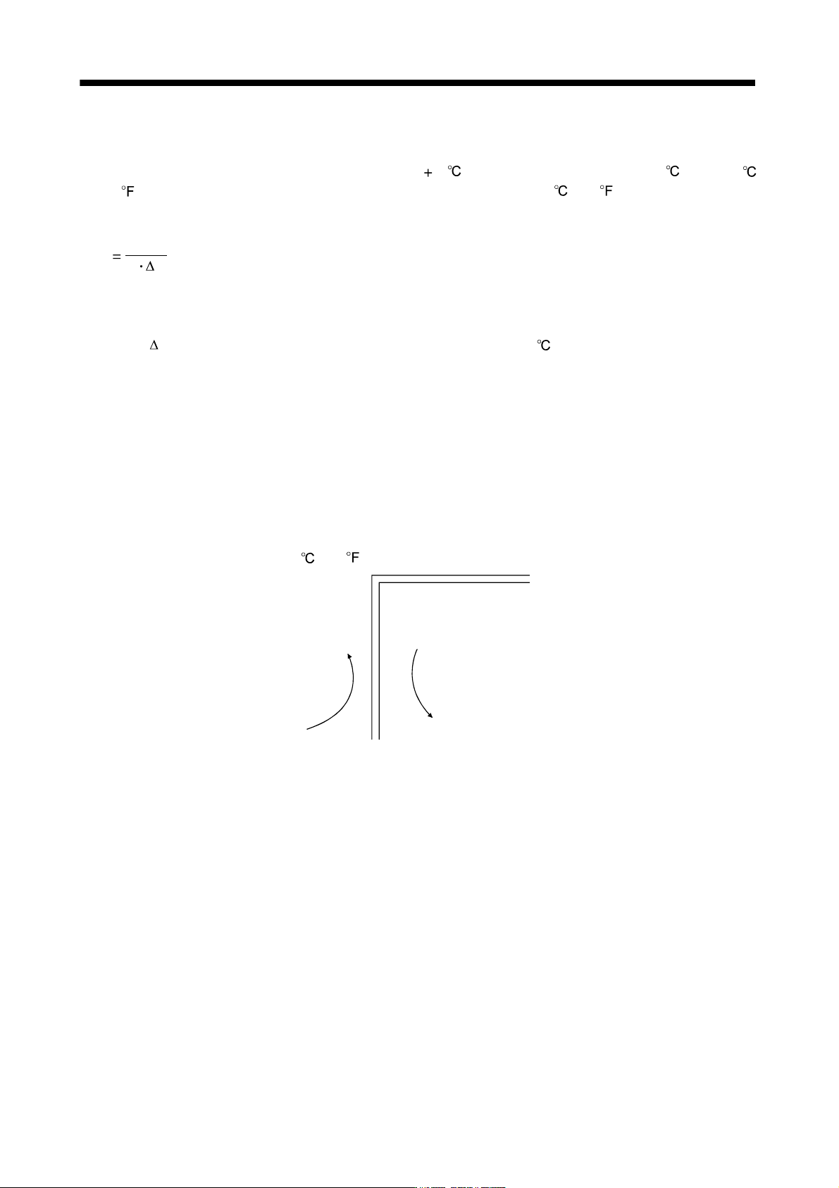
Table 10.1 lists the enclosure dissipation area for each servo amplifier when the servo amplifier is operated
at the ambient temperature of 40
(104 ) under rated load.
(Outside)
(Inside)
Air flow
Fig. 10.2 Temperature distribution in enclosure
When air flows along the outer wall of the enclosure, effective heat exchange will be possible, because the
temperature slope inside and outside the enclosure will be steeper.