sh030051g.pdf - 第262页
11 - 57 11. OPTIONS AND AUXILI ARY EQUIPMENT (2) Connection example NFB L 11 L 21 U V W U V W M Servo amplifier Servo motor RA2 MC SK MC ON OFF ALM RA1 Operation-ready EM1 L 3 L 2 L 1 (Note 5) Power supply 13 U 14 V W Ex…

11 - 56
11. OPTIONS AND AUXILIARY EQUIPMENT
11.6 External dynamic brake
POINT
Configure up a sequence which switches off the contact of the brake unit after
(or as soon as) it has turned off the servo on signal at a power failure or
failure.
For the braking time taken when the dynamic brake is operated, refer to
section 10.3.
The brake unit is rated for a short duration. Do not use it for high duty.
When using the 400V class dynamic brake, the power supply voltage is
restricted to 1-phase 380VAC to 463VAC (50Hz/60Hz).
(1) Selection of dynamic brake
The dynamic brake is designed to bring the servo motor to a sudden stop when a power failure occurs
or the protective circuit is activated, and is built in the 7kW or less servo amplifier. Since it is not built
in the 11kW or more servo amplifier, purchase it separately if required. Assign the dynamic brake interlock
(DB) to any of CN3-9, CN3-13, and CN3-15 pins in parameter No.PD07 to PD09.
Servo amplifier Dynamic brake
MR-J3-11KB DBU-11K
MR-J3-15KB DBU-15K
MR-J3-22KB DBU-22K
MR-J3-11KB4 DBU-11K-4
MR-J3-15KB4
DBU-22K-4
MR-J3-22KB4
11 - 57
11. OPTIONS AND AUXILIARY EQUIPMENT
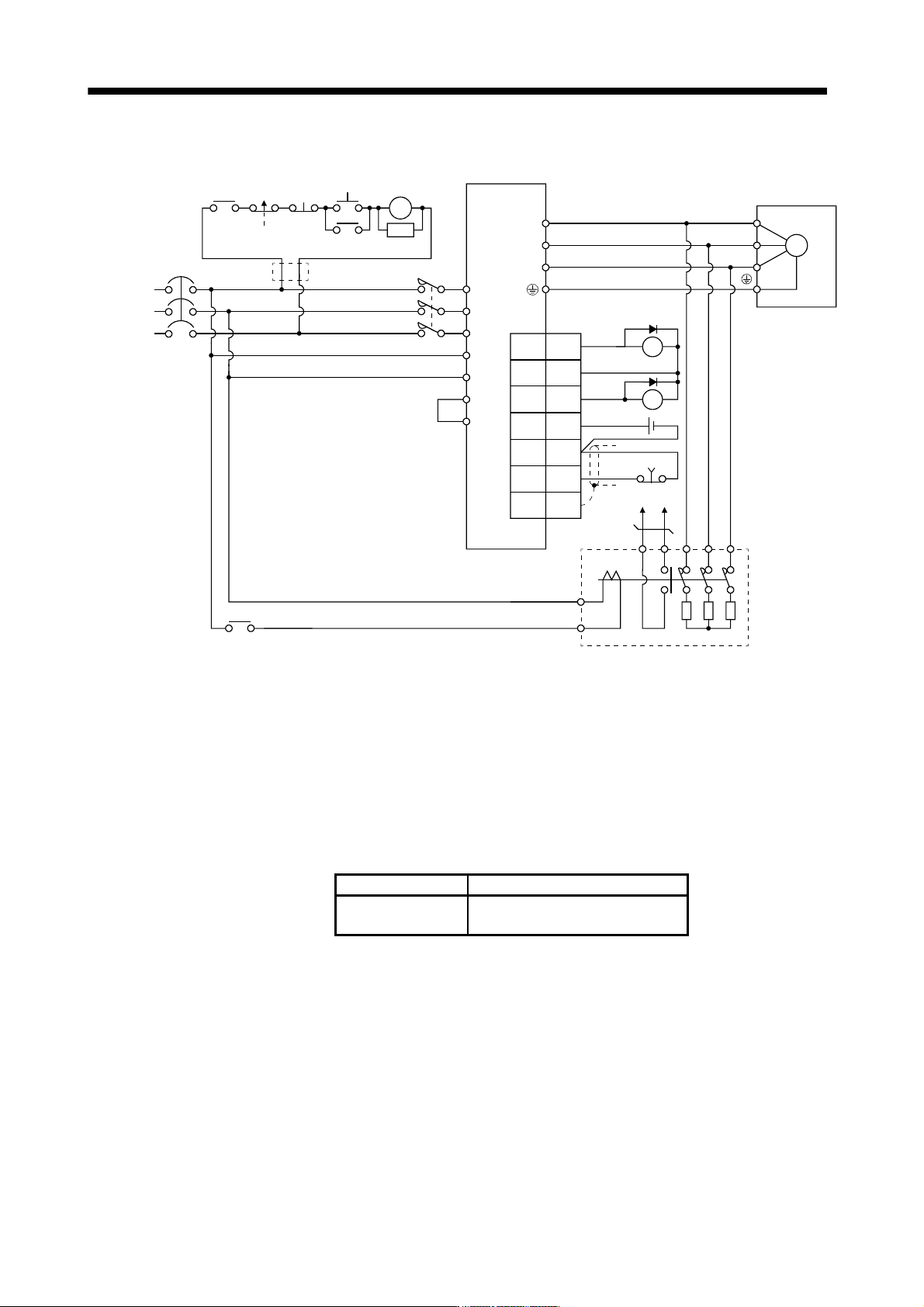
(2) Connection example
NFB
L11
L21
U
V
W
U
V
W
M
Servo amplifier
Servo motor
RA2
MC
SK
MC
ON
OFF
ALM
RA1
Operation-ready
EM1
L
3
L2
L
1
(Note 5)
Power
supply
13 U14 V W
External dynamic brake
a
b
(Note 1)
P
P
1
(Note 2)
(Note 4)
EM1
3
20
SDPlate
DICOM
10
DB
(Note 3)
DOCOM
5
DICOM
ALM15
CN3
RA1
RA2
MC
(Note 6)
Note 1. Terminals 13, 14 are normally open contact outputs. If the dynamic brake is seized, terminals 13, 14 will open.
Therefore, configure up an external sequence to prevent servo-on.
2. For the servo amplifiers from 11k to 22kW, be sure to connect P
1 and P. (Factory-wired)
When using the power factor DC reactor, refer to section 11.13.
3. Assign the dynamic brake interlock (DB) in the parameters No.PD07 to PD09.
4. Stepdown transformer is required for coil voltage of magnetic contactor more than 200V class in 400V class servo amplifiers.
5. Refer to section 1.3 for the power supply specification.
6. The power supply voltage of the inside magnet contactor for 400V class dynamic brake DBU-11K-4 and DBU-22K-4 is restricted
as follows. When using these dynamic brakes, use them within the range of the power supply.
Dynamic brake Power supply voltage
DBU-11K-4
DBU-22K-4
1-phase 380 to 463VAC 50Hz/60Hz
11 - 58
11. OPTIONS AND AUXILIARY EQUIPMENT
Servo motor rotation
Coasting
Alarm
RA1
ON
OFF
Forced stop
(EM1)
Absent
Invalid
Valid
Short
Open
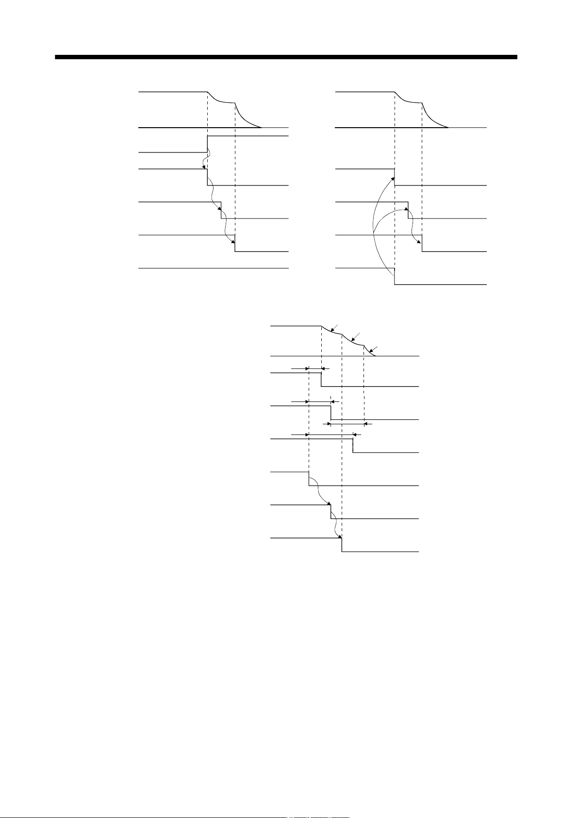
a. Timing chart at alarm occurrence b. Timing chart at forced stop (EM1) validit
y
Dynamic brake
Base
ON
OFF
Coasting
Dynamic brake
Dynamic brake
Present
(Note 2)15 to 60ms
(Note 1)7ms
10ms
Dynamic brake
Coasting
Electro magnetic
brake interlock
Electro magnetic
brake operation
delay time
Electro magnetic
brake interlock(MBR)
Base circuit
ON
OFF
Servo motor speed
Alarm
Main circuit
Control circuit
ON
OFF
Power
RA1
Dynamic brake
ON
OFF
Invalid (ON)
Valid (OFF)
Invalid
Valid
Invalid (ON)
Valid (OFF)
Note 1. When powering OFF, the RA1 of external dynamic brake circuit will be turned OFF, and the base circuit
is turned OFF earlier than usual before an output shortage occurs.
(Only when assigning the DB as the output signal in the parameter No.PD07, PD08 or PD09)
2. Variable according to the operation status.
c. Timing chart when both of the main and control circuit power are OFF