sh030051g.pdf - 第123页
5 - 6 5. PARAMETERS 5.1.6 Auto tuning Parameter Initial value Unit Setting range No. Symbol Name PA08 ATU Auto tuning mode 0001h Refer to the text. PA09 RSP Auto tuning response 12 1 to 32 Make gain adjustment using auto…
5 - 5
5. PARAMETERS
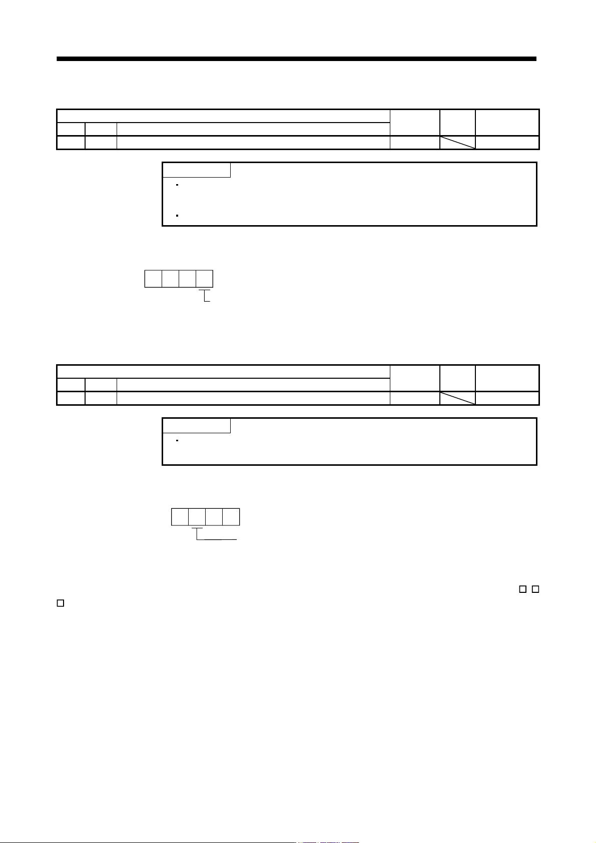
5.1.4 Using absolute position detection system
Parameter
Initial value Unit Setting range
No. Symbol Name
PA03 *ABS Absolute position detection system 0000h Refer to the text.
POINT
This parameter is made valid when power is switched off, then on after
setting, or when the controller reset has been performed.
This parameter cannot be used in the speed control mode.
Set this parameter when using the absolute position detection system in the position control mode.
Selection of absolute position detection system (refer to chapter 12)
0: Used in incremental system
1: Used in absolute position detection system
Parameter No.PA03
000
5.1.5 Forced stop input selection
Parameter
Initial value Unit Setting range
No. Symbol Name
PA04 *AOP1 Function selection A-1 0000h Refer to the text.
POINT
This parameter is made valid when power is switched off, then on after
setting, or when the controller reset has been performed.
The servo forced stop function is avoidable.
Selection of servo forced stop
0: Valid (Forced stop (EM1) is used.)
1: Invalid (Forced stop (EM1) is not used.)
Parameter No.PA04
000
When not using the forced stop (EM1) of servo amplifier, set the selection of servo forced stop to Invalid (
1
). At this time, the forced stop (EM1) automatically turns on inside the servo amplifier.
5 - 6
5. PARAMETERS
5.1.6 Auto tuning
Parameter
Initial value Unit Setting range
No. Symbol Name
PA08 ATU Auto tuning mode 0001h Refer to the text.
PA09 RSP Auto tuning response 12 1 to 32
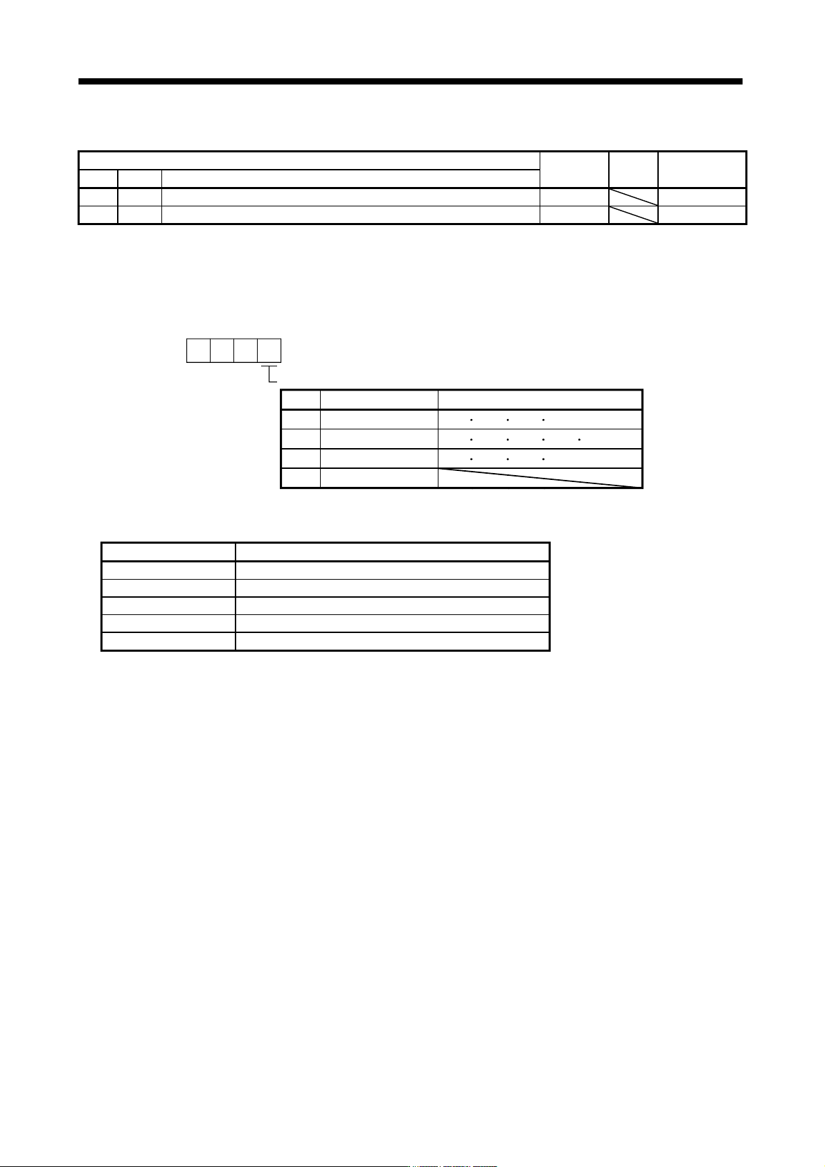
Make gain adjustment using auto tuning. Refer to section 6.2 for details.
(1) Auto tuning mode (parameter No.PA08)
Select the gain adjustment mode.
Gain adjustment mode setting
Parameter No.PA08
000
Setting Gain adjustment mode Automatically set parameter No. (Note)
Interpolation mode
Auto tuning mode 1
Auto tuning mode 2
Manual mode
0
1
2
3
PB06 PB08 PB09 PB10
PB06 PB07 PB08 PB09 PB10
PB07 PB08 PB09 PB10
Note. The parameters have the following names.
Parameter No. Name
PB06 Ratio of load inertia moment to servo motor inertia moment
PB07 Model loop gain
PB08 Position loop gain
PB09 Speed loop gain
PB10 Speed integral compensation
5 - 7
5. PARAMETERS
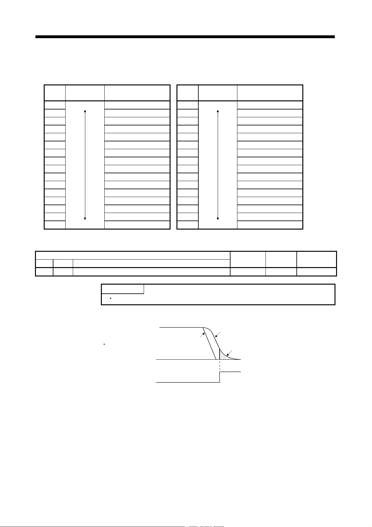
(2) Auto tuning response (parameter No.PA09)
If the machine hunts or generates large gear sound, decrease the set value. To improve performance, e.g.
shorten the settling time, increase the set value.
Setting Response
Guideline for machine
resonance frequency [Hz]
Setting Response
Guideline for machine
resonance frequency [Hz]
1 Low response 10.0 17 Low response 67.1
2
11.3 18
75.6
3 12.7 19 85.2
4 14.3 20 95.9
5 16.1 21 108.0
6 18.1 22 121.7
7 20.4 23 137.1
8 23.0 24 154.4
9 25.9 25 173.9
10 29.2 26 195.9
11 32.9 27 220.6
12 37.0 28 248.5
13 41.7 29 279.9
14 47.0 30 315.3
15 52.9 31 355.1
16 Middle response 59.6 32 Middle response 400.0
5.1.7 In-position range
Parameter
Initial value Unit Setting range
No. Symbol Name
PA10 INP In-position range 100 pulse 0 to 65535
POINT
This parameter cannot be used in the speed control mode.
Set the range, where in position (INP) is output, in the command pulse unit.
Servo motor droop pulse
In-position range [pulse]
Command pulse
Command pulse
Droop pulse
In position (INP)
ON
OFF