sh030051g.pdf - 第195页
9 - 12 9. OUTLINE DRAWINGS MEMO
9 - 11
9. OUTLINE DRAWINGS
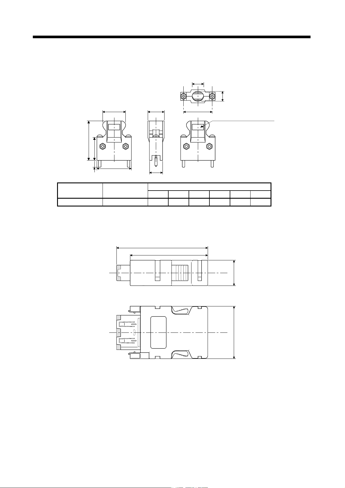
(b) Jack screw M2.6 type
This is not available as option.
[Unit: mm]
E
B
A
23.8
39.0
12.7
C
D
5.2
F
Logo etc, are indicated here.
Connector Shell kit
Each type of dimension
A B C D E F
10120-3000PE 10320-52F0-008 22.0 33.3 14.0 10.0 12.0 27.4
(3) SCR connector system (3M)
Receptacle : 36210-0100PL
Shell kit : 36310-3200-008
34.8
39.5
22.4
11.0

9 - 12
9. OUTLINE DRAWINGS
MEMO
10 - 1
10. CHARACTERISTICS
10. CHARACTERISTICS
10.1 Overload protection characteristics
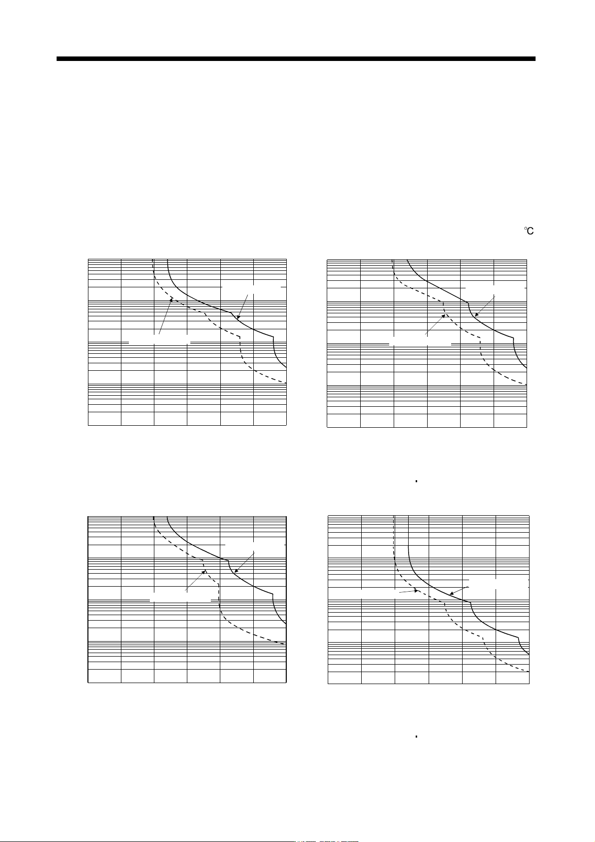
An electronic thermal relay is built in the servo amplifier to protect the servo motor and servo amplifier from
overloads. Overload 1 alarm (50) occurs if overload operation performed is above the electronic thermal relay
protection curve shown in any of Figs 10.1. Overload 2 alarm (51) occurs if the maximum current flew
continuously for several seconds due to machine collision, etc. Use the equipment on the left-hand side area of
the continuous or broken line in the graph.
In a machine like the one for vertical lift application where unbalanced torque will be produced, it is
recommended to use the machine so that the unbalanced torque is 70% or less of the rated torque.
When you carry out adhesion mounting of the servo amplifier, make circumference temperature into 0 to 45
,
or use it at 75% or smaller effective load ratio.
1000
100
10
1
0.1
0 50 150 200 250 300100
(Note) Load ratio [%]
Operation time[s]
During operation
During servo lock
MR-J3-10B(1)
1000
100
10
1
0.1
0 50 150 200 250 300
100
(Note) Load ratio [%]
Operation time[s]
During operation
During servo lock
MR-J3-20B(1) MR-J3-40B(1)
MR-J3-60B(4) to MR-J3-100B(4)
1000
100
10
1
0.1
0 50 150 200 250 300
100
(Note) Load ratio [%]
Operation time[s]
During operation
During servo lock
MR-J3-200B(4) to MR-J3-350B(4)
(Note) Load ratio [%]
Operation time[s]
10000
1000
100
10
1
0 50 150 200 250100 300
During operation
During servo lock
MR-J3-500B(4) MR-J3-700B(4)