sh030051g.pdf - 第176页
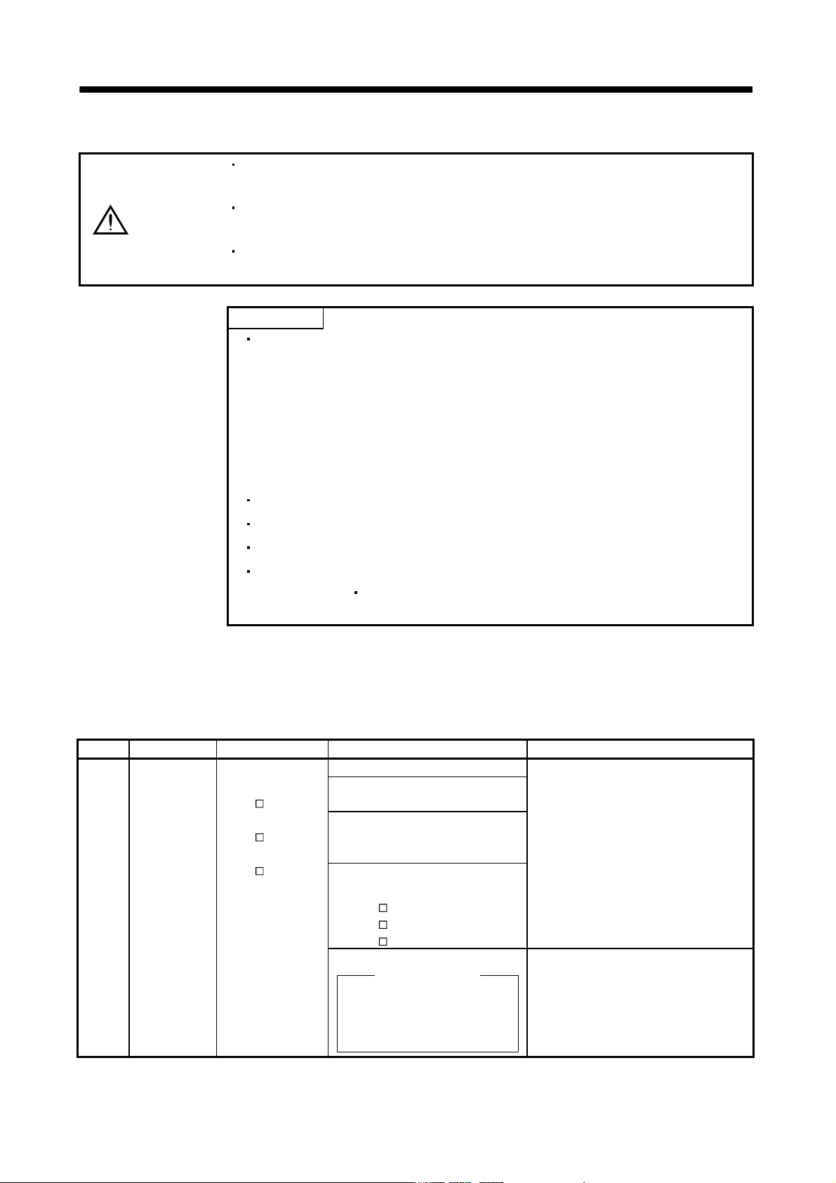
8 - 3 8. TROUBLESHOOTING Display Name Definition Cause Action 12 Memory erro r 1 (RAM) RAM, memory fault Faulty parts in the servo amplifier Check ing method Alar m (any of 12 an d 13) occurs if power is switched on afte…
8 - 2
8. TROUBLESHOOTING
8.2 Remedies for alarms
CAUTION
When any alarm has occurred, eliminate its cause, ensure safety, then reset the
alarm, and restart operation. Otherwise, injury may occur.
If an absolute position erase (25) occurred, always make home position setting
again. Not doing so may cause unexpected operation.
As soon as an alarm occurs, mark Servo-off and power off the main circuit and
control circuit.
POINT
When any of the following alarms has occurred, do not deactivate the alarm
and resume operation repeatedly. To do so will cause the servo amplifier/servo
motor to fail. Remove the cause of occurrence, and leave a cooling time of
more than 30 minutes before resuming operation. To protect the main circuit
elements, any of these servo alarms cannot be deactivated from the servo
system controller until the specified time elapses after its occurrence. Judging
the load changing condition until the alarm occurs, the servo amplifier
calculates this specified time automatically.
Regenerative error (30)
Overload 1 (50)
Overload 2 (51)
The alarm can be deactivated by switching power off, then on or by the error
reset command
CPU reset from the servo system controller. For details, refer
to section 8.1.
When an alarm occurs, the trouble (ALM) switches off and the dynamic brake is operated to stop the servo
motor. At this time, the display indicates the alarm No.
The servo motor comes to a stop. Remove the cause of the alarm in accordance with this section. Use the MR
Configurator to refer to a factor of alarm occurrence.
Display Name Definition Cause Action
10 Undervoltage Power supply voltage
dropped.
MR-J3-
B:
160VAC or less
MR-J3-
B1:
83VAC or less
MR-J3-
B4:
280VAC or less
1. Power supply voltage is low. Check the power supply.
2. There was an instantaneous control
power failure of 60ms or longer.
3. Shortage of power supply capacity
caused the power supply voltage to
drop at start, etc.
4. The bus voltage dropped to the
following value or less.
MR-J3-
B: 200VDC
MR-J3-
B1: 158VDC
MR-J3-
B4: 380VDC
5. Faulty parts in the servo amplifier
Checking method
Alarm (10) occurs if power is
switched on after disconnection
of all cables but the control
circuit power supply cables.
Change the servo amplifier.
8 - 3
8. TROUBLESHOOTING
Display Name Definition Cause Action
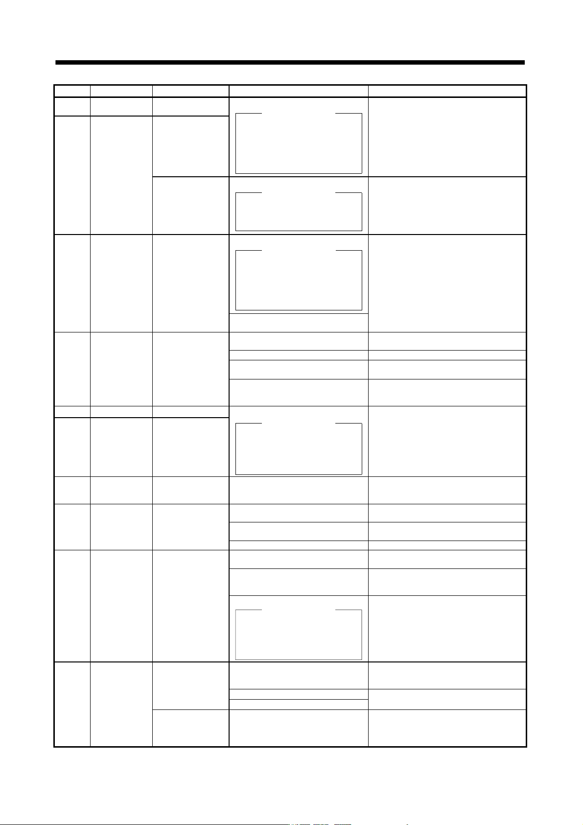
12 Memory error 1
(RAM)
RAM, memory fault Faulty parts in the servo amplifier
Checking method
Alarm (any of 12 and 13)
occurs if power is switched on
after disconnection of all cables
but the control circuit power
supply cables.
Change the servo amplifier.
13 Clock error Printed board fault
Clock error
transmitted from the
controller
Faulty controller
Checking method
Alarm (13) occurs, if servo
controller is used in multiple CPU
system.
Change the servo system controller.
15 Memory error 2
(EEP-ROM)
EEP-ROM fault
1. Faulty parts in the servo amplifier
Checking method
Alarm (15)
occurs if power is switched on
after disconnection of all cables
but the control circuit power
supply cables.
Change the servo amplifier.
2. The number of write times to EEP-
ROM exceeded 100,000.
16 Encoder error 1
(At power on)
Communication error
occurred between
encoder and servo
amplifier.
1. Encoder connector (CN2)
disconnected.
Connect correctly.
2. Encoder fault Change the servo motor.
3. Encoder cable faulty
(Wire breakage or shorted)
Repair or change the cable.
4. Encoder cable type (2-wire, 4-wire)
selection was wrong in parameter
setting.
Correct the setting in the fourth digit of
parameter No.PC04.
17 Board error 2 CPU/parts fault
Faulty parts in the servo amplifier
Checking method
Alarm (17 or 19) occurs if
power is switched on after
disconnection of all cables but the
control circuit power supply cable.
Change the servo amplifier.
19 Memory error 3
(Flash ROM)
ROM memory fault
1A Motor
combination
error
Wrong combination
of servo amplifier
and servo motor.
Wrong combination of servo amplifier
and servo motor connected.
Use correct combination.
20 Encoder error 2 Communication error
occurred between
encoder and servo
amplifier.
1. Encoder connector (CN2)
disconnected.
Connect correctly.
2. Encoder cable faulty
(Wire breakage or shorted)
Repair or change the cable.
3. Encoder fault Change the servo motor.
24 Main circuit error Ground fault
occurred at the servo
motor power (U,V
and W phases) of
the servo amplifier.
1. Power input wires and servo motor
power wires are in contact.
Connect correctly.
2. Sheathes of servo motor power
cables deteriorated, resulting in
ground fault.
Change the cable.
3. Main circuit of servo amplifier failed.
Checking method
Alarm (24) occurs if the servo is
switched on after disconnecting
the U, V, W power cables from
the servo amplifier.
Change the servo amplifier.
25 Absolute
position erase
Absolute position
data in error
1. Voltage drop in encoder
(Battery disconnected.)
After leaving the alarm occurring for a few
minutes, switch power off, then on again.
Always make home position setting again.
2. Battery voltage low Change the battery.
Always make home position setting again.
3. Battery cable or battery is faulty.
Power was switched
on for the first time in
the absolute position
detection system.
4. Home position not set. After leaving the alarm occurring for a few
minutes, switch power off, then on again.
Always make home position setting again.
8 - 4
8. TROUBLESHOOTING
Display Name Definition Cause Action
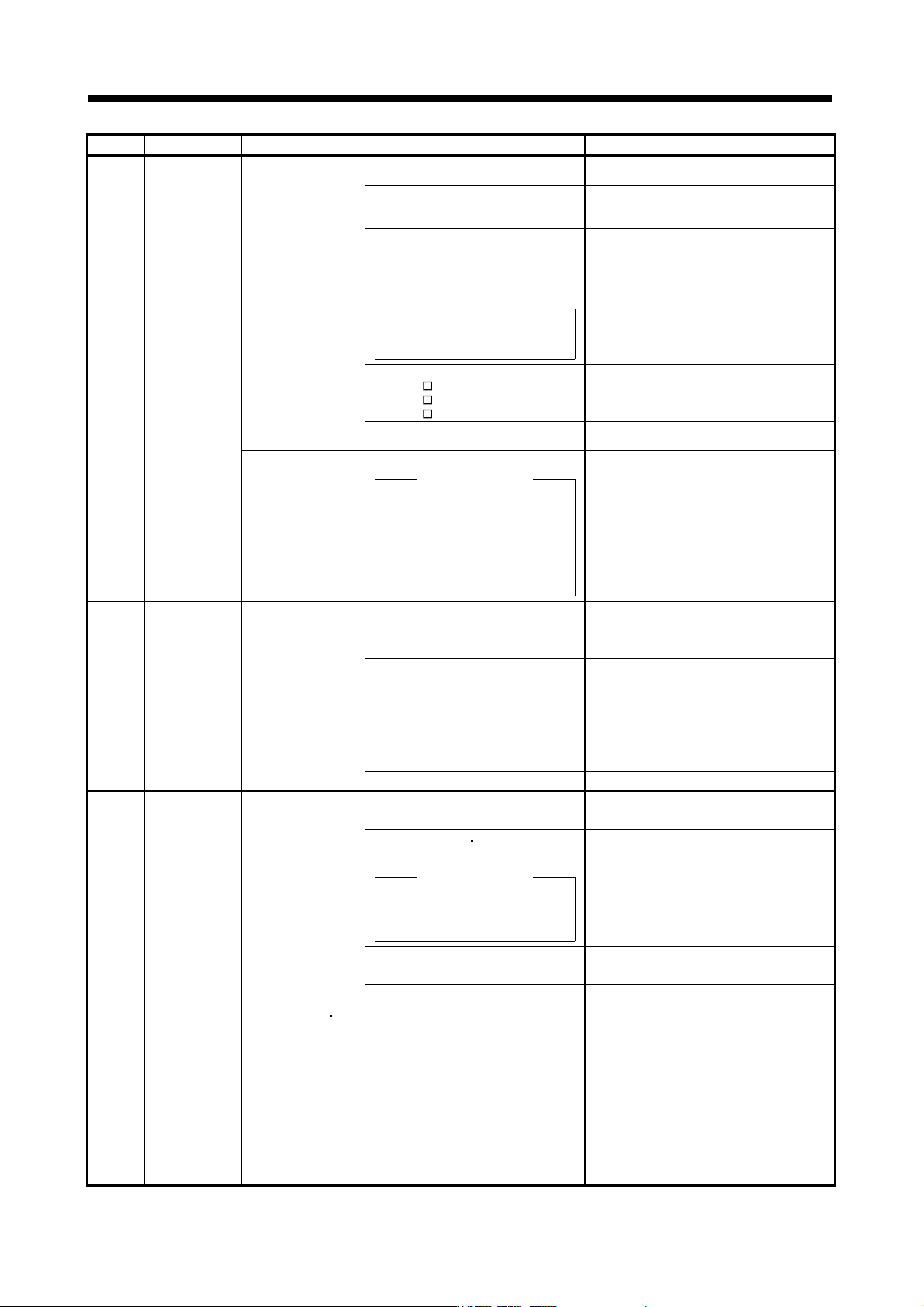
30 Regenerative
error
Permissible
regenerative power
of the built-in
regenerative resistor
or regenerative
option is exceeded.
1. Wrong setting of parameter No.
PA02
Set correctly.
2. Built-in regenerative resistor or
regenerative option is not
connected.
Connect correctly.
3. High-duty operation or continuous
regenerative operation caused the
permissible regenerative power of
the regenerative option to be
exceeded.
Checking method
Call the status display and check
the regenerative load ratio.
1. Reduce the frequency of positioning.
2. Use the regenerative option of larger
capacity.
3. Reduce the load.
4. Power supply voltage is abnormal.
MR-J3-
B:260VAC or more
MR-J3-
B1:More than 135VAC
MR-J3-
B4: 535VAC or more
Check the power supply.
5. Built-in regenerative resistor or
regenerative option faulty.
Change the servo amplifier or regenerative
option.
Regenerative
transistor fault
6. Regenerative transistor faulty.
Checking method
1) The regenerative option has
overheated abnormally.
2) The alarm occurs even after
removal of the built-in
regenerative resistor or
regenerative option.
Change the servo amplifier.
31 Overspeed Speed has exceeded
the instantaneous
permissible speed.
1. Small acceleration/deceleration time
constant caused overshoot to be
large.
Increase acceleration/deceleration time
constant.
2. Servo system is instable to cause
overshoot.
1. Re-set servo gain to proper value.
2. If servo gain cannot be set to proper
value.
1) Reduce load inertia moment ratio; or
2) Reexamine acceleration/
deceleration time constant.
3. Encoder faulty. Change the servo motor.
32 Overcurrent
Current that flew is
higher than the
permissible current of
the servo amplifier.
(If the alarm (32)
occurs again when
turning ON the servo
after resetting the
alarm by turning
OFF/ON the power
when the alarm (32)
first occurred, the
transistor (IPM
IGBT) of the servo
amplifier may be at
fault. In the case, do
not repeat to turn
OFF/ON the power.
Check the transistor
with the checking
method of “Cause
2”.)
1. Short occurred in servo motor power
(U, V, W).
Correct the wiring.
2. Transistor (IPM IGBT) of the servo
amplifier faulty.
Checking method
Alarm (32) occurs if power is
switched on after U,V and W are
disconnected.
Change the servo amplifier.
3. Ground fault occurred in servo
motor power (U, V, W).
Correct the wiring.
4. External noise caused the
overcurrent detection circuit to
misoperate.
Take noise suppression measures.