sh030051g.pdf - 第87页
3 - 32 3. SIGNALS AND WI RING 3.8 Treatment of cable shield external condu ctor In the case of the CN2 and CN3 connectors, securely c onnect the s hielded external conductor of the cable to the ground plate as shown in t…
3 - 31
3. SIGNALS AND WIRING
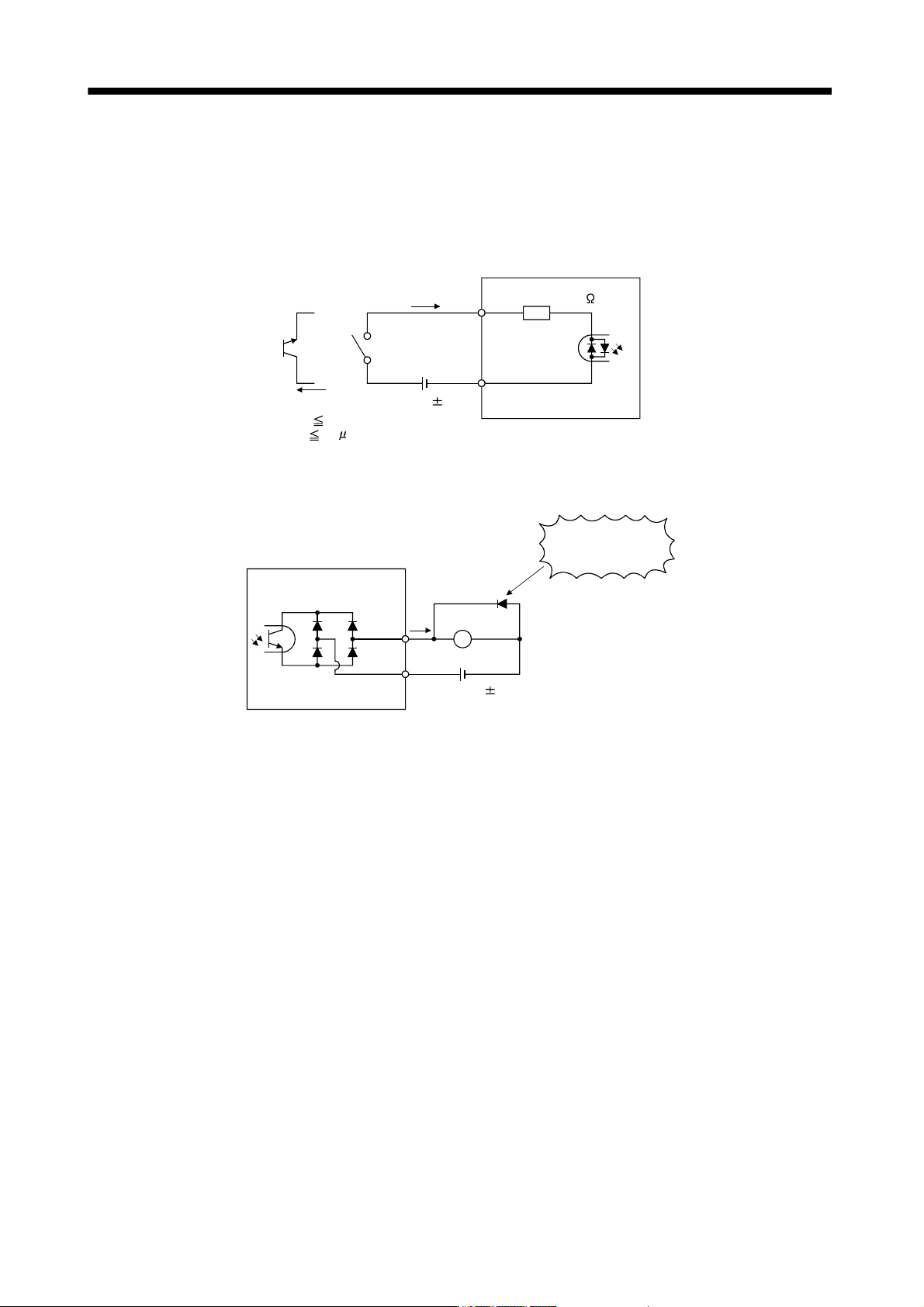
3.7.3 Source I/O interfaces
In this servo amplifier, source type I/O interfaces can be used. In this case, all DI-1 input signals and DO-1
output signals are of source type. Perform wiring according to the following interfaces.
(1) Digital input interface DI-1
EM1,
etc.
Servo amplifier
Switch
Approx. 5mA
DICOM
V
CES 1.0V
I
CEO
100
A
24VDC 10%
150mA
Approx. 5.6k
(2) Digital output interface DO-1
A maximum of 2.6V voltage drop occurs in the servo amplifier.
If polarity of diode is
reversed, servo
amplifier will fail.
Servo amplifier
ALM,
etc.
Load
DOCOM
24VDC 10%
150mA
(Note)
Note. If the voltage drop (maximum of 2.6V) interferes with the relay operation, apply high voltage (up to
26.4V) from external source.
3 - 32
3. SIGNALS AND WIRING
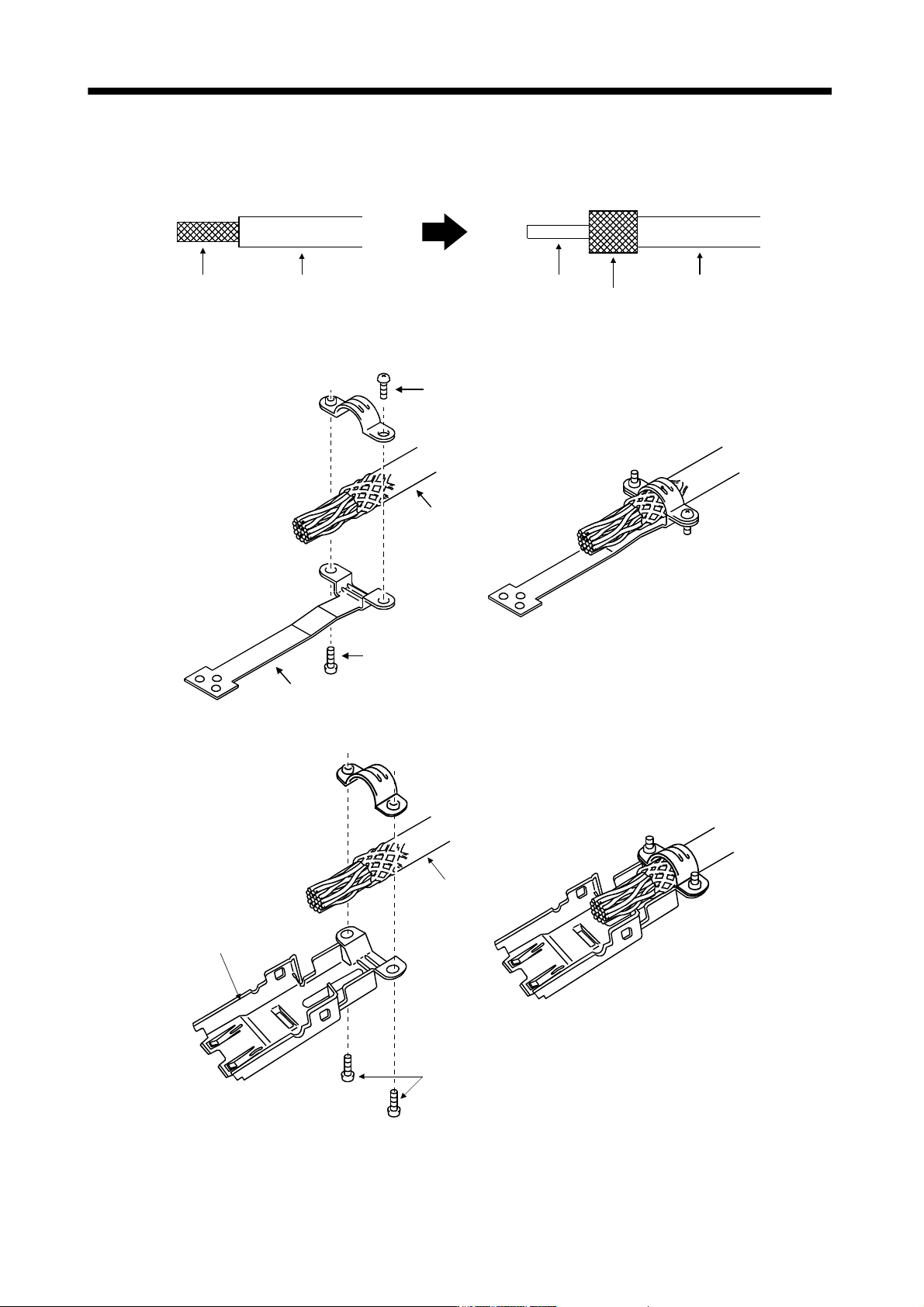
3.8 Treatment of cable shield external conductor
In the case of the CN2 and CN3 connectors, securely connect the shielded external conductor of the cable to
the ground plate as shown in this section and fix it to the connector shell.
External conductor Sheath
External conductor
Pull back the external conductor to cover the sheath
SheathCore
Strip the sheath.
(1) For CN3 connector (3M connector)
Screw
Screw
Ground plate
Cable
(2) For CN2 connector (3M or Molex connector)
Screw
Cable
Ground plate
3 - 33
3. SIGNALS AND WIRING
3.9 SSCNET
cable connection
POINT
Do not see directly the light generated from CN1A CN1B connector of servo
amplifier or the end of SSCNET
cable.
When the light gets into eye, may feel something is wrong for eye.
(The light source of SSCNET
complies with class1 defined in JIS C6802 or
IEC60825-1.)
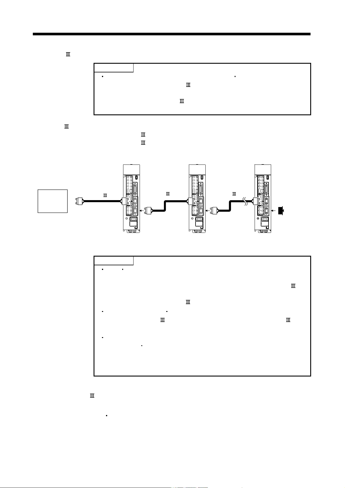
(1) SSCNET
cable connection
For CN1A connector, connect SSCNET
cable connected to controller in host side or servo amplifier.
For CN1B connector, connect SSCNET
cable connected to servo amplifier in lower side.
For CN1B connector of the final axis, put a cap came with servo amplifier.
SSCNET cable
CN1B
CN1A
CN1B
CN1A
Controller
Axis No.1 servo amplifier Axis No.2 servo amplifier Final axis servo amplifier
CN1B
CN1A
Cap
SSCNET cable SSCNET cable
(2) How to connect/disconnect cable.
POINT
CN1A CN1B connector is put a cap to protect light device inside connector
from dust.
For this reason, do not remove a cap until just before mounting SSCNET
cable.
Then, when removing SSCNET
cable, make sure to put a cap.
Keep the cap for CN1A CN1B connector and the tube for protecting light
code end of SSCNET
cable in a plastic bag with a zipper of SSCNET
cable to prevent them from becoming dirty.
When asking repair of servo amplifier for some troubles, make sure to put a
cap on CN1A
CN1B connector.
When the connector is not put a cap, the light device may be damaged at the
transit.
In this case, exchange and repair of light device is required.
(a) Mounting
1) For SSCNET
cable in the shipping status, the tube for protect light code end is put on the end of
connector. Remove this tube.
2) Remove the CN1A
CN1B connector cap of servo amplifier.