sh030051g.pdf - 第136页
5 - 19 5. PARAMETERS 5.3.2 List of details No. Symbol Name and function Initial value Unit Setting range PC01 ERZ (Note 2) Error excessive alarm level This parameter cannot be used in the speed control mode. Set error ex…
5 - 18
5. PARAMETERS
5.3 Extension setting parameters (No.PC
)
POINT
Parameter whose symbol is preceded by * is made valid with the following
conditions.
* : Set the parameter value, switch power off once after setting, and then
switch it on again, or perform the controller reset.
**: Set the parameter value, switch power off once, and then switch it on
again.
5.3.1 Parameter list
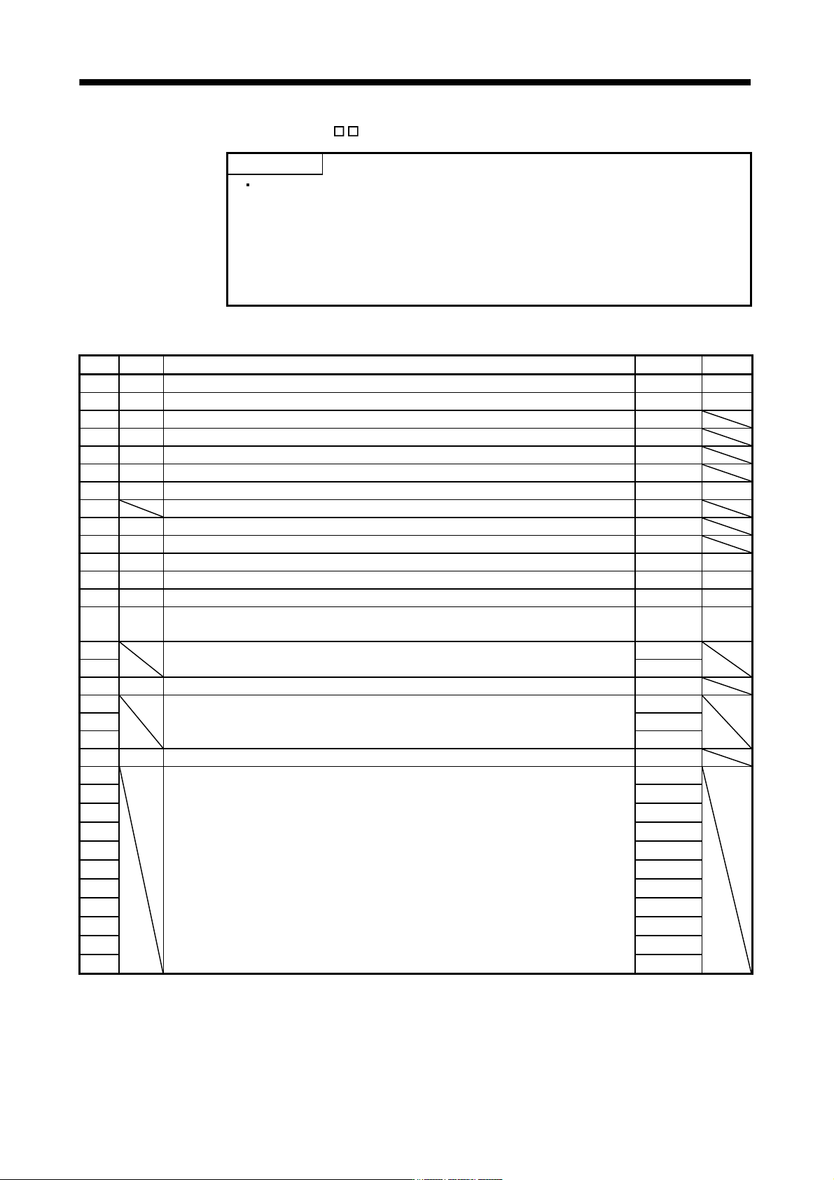
No. Symbol Name Initial value Unit
PC01 ERZ Error excessive alarm level 3 rev
PC02 MBR Electromagnetic brake sequence output 0 ms
PC03 *ENRS Encoder output pulses selection 0000h
PC04 **COP1 Function selection C-1 0000h
PC05 **COP2 Function selection C-2 0000h
PC06 *COP3 Function selection C-3 0000h
PC07 ZSP Zero speed 50 r/min
PC08 For manufacturer setting 0
PC09 MOD1 Analog monitor 1 output 0000h
PC10 MOD2 Analog monitor 2 output 0001h
PC11 MO1 Analog monitor 1 offset 0 mV
PC12 MO2 Analog monitor 2 offset 0 mV
PC13 MOSDL Analog monitor feedback position output standard data Low 0 pulse
PC14 MOSDH Analog monitor feedback position output standard data High 0 10000
pulse
PC15
For manufacturer setting 0
PC16 0000h
PC17 **COP4 Function selection C-4 0000h
PC18
For manufacturer setting 0000h
PC19 0000h
PC20 0000h
PC21 *BPS Alarm history clear 0000h
PC22
For manufacturer setting 0000h
PC23 0000h
PC24 0000h
PC25 0000h
PC26 0000h
PC27 0000h
PC28 0000h
PC29 0000h
PC30 0000h
PC31 0000h
PC32 0000h
5 - 19
5. PARAMETERS
5.3.2 List of details
No. Symbol Name and function
Initial
value
Unit
Setting
range
PC01 ERZ
(Note 2)
Error excessive alarm level
This parameter cannot be used in the speed control mode.
Set error excessive alarm level with rotation amount of servo motor.
Note 1. Setting can be changed in parameter No.PC06.
2. For a servo amplifier with software version of B2 or later, reactivating the power
supply to enable the setting value is not necessary. For a servo amplifier with
software version of earlier than B2, reactivating the power supply is required to
enable the setting value.
3 rev
(Note 1)
1
to
200
PC02 MBR Electromagnetic brake sequence output
Used to set the delay time (Tb) between electronic brake interlock (MBR) and the base
drive circuit is shut-off.
0 ms 0
to
1000
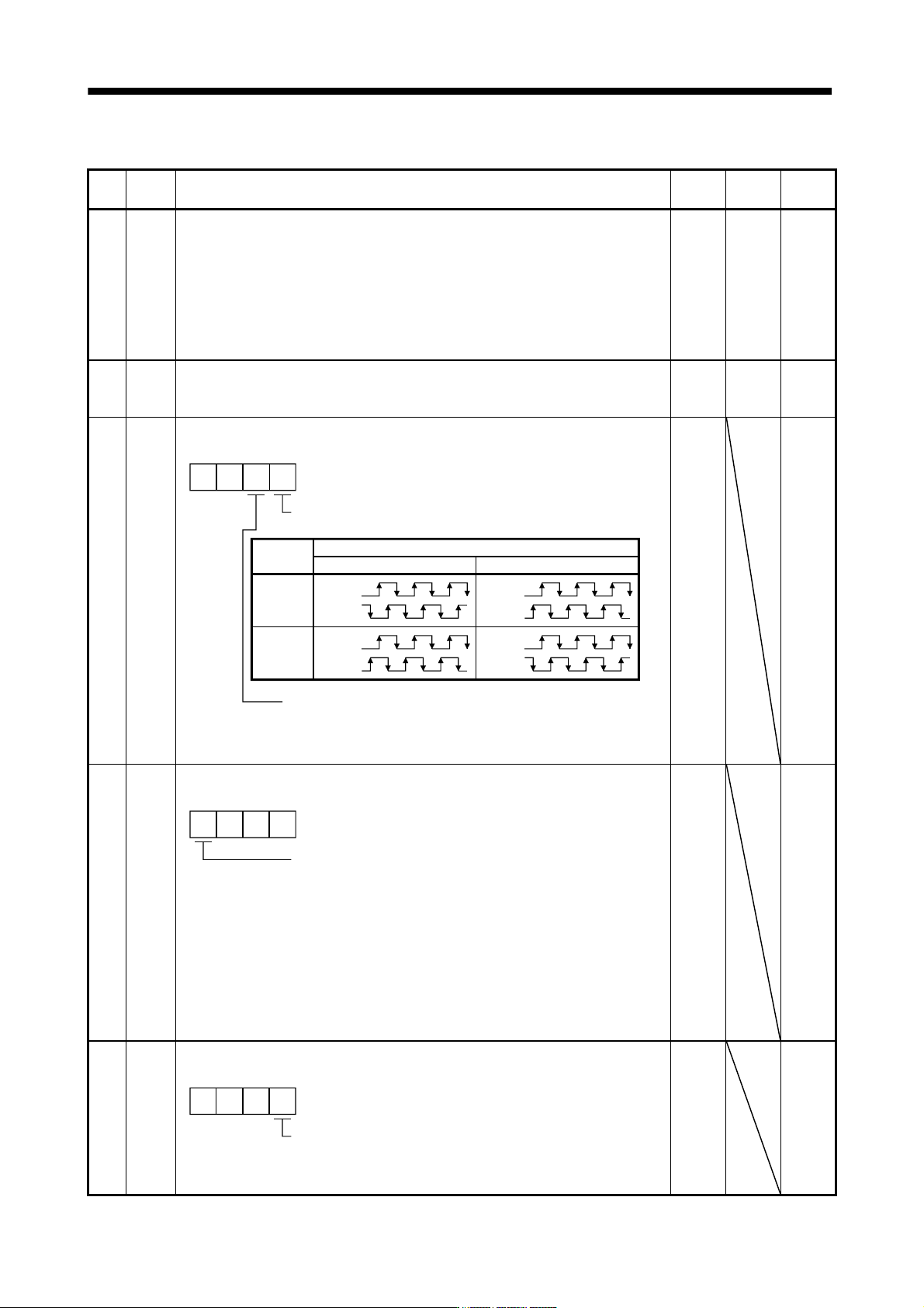
PC03 *ENRS Encoder output pulse selection
Use to select the, encoder output pulse direction and encoder output pulse setting.
CW
Encoder output pulse phase changing
Changes the phases of A, B-phase encoder pulses output .
A-phase
B-phase
CCW
Servo motor rotation direction
Set value
0
1
Encoder output pulse setting selection (refer to parameter No.PA15)
0: Output pulse designation
1: Division ratio setting
00
A-phase
B-phase
A-phase
B-phase
A-phase
B-phase
0000h Refer to
Name
and
function
column.
PC04 **COP1 Function selection C-1
Select the encoder cable communication system selection.
00
Encoder cable communication system selection
0: Two-wire type
1: Four-wire type
The following encoder cables are of 4-wire type.
MR-EKCBL30M-L
MR-EKCBL30M-H
MR-EKCBL40M-H
MR-EKCBL50M-H
The other encoder cables are all of 2-wire type.
Incorrect setting will result in an encoder alarm 1 (16) or encoder
alarm 2 (20).
0
0000h Refer to
Name
and
function
column.
PC05 **COP2 Function selection C-2
Motor-less operation select.
Motor-less operation select.
0: Valid
1: Invalid
000
0000h Refer to
Name
and
function
column.
5 - 20
5. PARAMETERS
No. Symbol Name and function
Initial
value
Unit
Setting
range
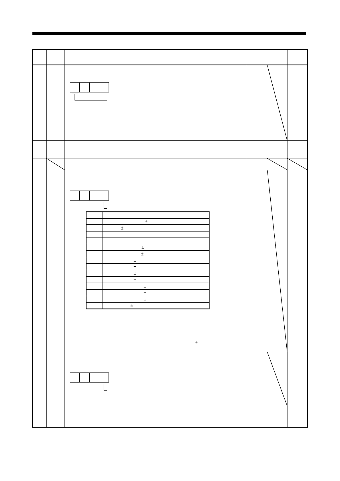
PC06 *COP3
Function selection C-3
Select the error excessive alarm level setting for parameter No.PC01.
00
Error excessive alarm level setting selection
0: 1 [rev]unit
1: 0.1 [rev]unit
2: 0.01 [rev]unit
3: 0.001[rev]unit
0
This parameter is available to software version B1 or later.
0000h Refer to
Name
and
function
column.
PC07 ZSP Zero speed
Used to set the output range of the zero speed (ZSP).
Zero speed signal detection has hysteresis width of 20r/min (Refer to section 3.5 (2) (b))
50 r/min 0
to
10000
PC08 For manufacturer setting
Do not change this value by any means.
0
PC09 MOD1
Analog monitor 1 output
Used to selection the signal provided to the analog monitor 1 (MO1) output. (Refer to
section 5.3.3)
C
B
5
6
7
8
9
A
D
0
1
2
3
4
Analog monitor 1 (MO1) output selection
0
Setting
Feedback position ( 10V/100 Mpulses) (Note 1, 3)
Servo motor speed ( 8V/max. speed)
Torque ( 8V/max. torque) (Note 2)
Servo motor speed (+8V/max. speed)
Torque (+8V/max. torque) (Note 2)
Current command ( 8V/max. current command)
Speed command ( 8V/max. current command)
Droop pulses ( 10V/100 pulses) (Note 1)
Droop pulses ( 10V/1000 pulses) (Note 1)
Droop pulses ( 10V/10000 pulses) (Note 1)
Droop pulses ( 10V/100000 pulses) (Note 1)
Feedback position ( 10V/1 Mpulses) (Note 1, 3)
Feedback position ( 10V/10 Mpulses) (Note 1, 3)
Bus voltage ( 8V/400V)(Note 4)
Item
00
Note 1. Encoder pulse unit.
2. 8V is outputted at the maximum torque.
3. It can be used by the absolute position detection system.
4. For 400V class servo amplifier, the bus voltage becomes
8V/800V.
0000h Refer to
Name
and
function
column.
PC10 MOD2
Analog monitor 2 output
Used to selection the signal provided to the analog monitor 2 (MO2) output. (Refer to
section 5.3.3)
Select the analog monitor 2 (MO2) output
The settings are the same as those of parameter No.PC09.
000
0001h Refer to
Name
and
function
column.
PC11 MO1 Analog monitor 1 offset
Used to set the offset voltage of the analog monitor 1 (MO1) output.
0 mV -999
to
999