sh030051g.pdf - 第265页
11 - 60 11. OPTIONS AND AUXILI ARY EQUIPMENT (b) DBU-11K-4 DBU-22K-4 [Unit: mm] 15 51 25 15 73.75 7 25 150 10 200 170 178.5 179.5 15 260 280 43 10 2- 7mount ing hole 195 228 26 26 210 2.3 Mass: 6.7[kg] a TE1 Tightening t…
11 - 59
11. OPTIONS AND AUXILIARY EQUIPMENT
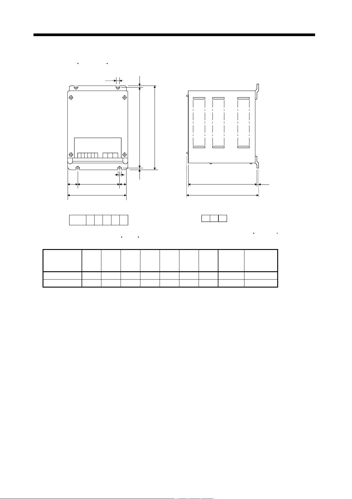
(3) Outline dimension drawing
(a) DBU-11K
DBU-15K DBU-22K
UVW
D
100
D
5
C
E
G
F
2.3
Terminal block
Screw : M3.5
Screw : M4
B
A
5
E
13 14
E
(GND)
ab
[Unit: mm]
Tightening torque: 1.2 [N m](10.6 [lb in])
Tightening torque: 0.8 [N m](7 [lb in])
Dynamic brake A B C D E F G
Mass
[kg]([Ib])
Connection
wire [mm
2
]
(Note)
DBU-11K 200 190 140 20 5 170 163.5 2 (4.41) 5.5
DBU-15K, 22K 250 238 150 25 6 235 228 6 (13.23) 5.5
Note. Selection condition of wire size is as follows.
Wire type: 600V Polyvinyl chloride insulated wire (IV wire)
Construction condition: One wire is constructed in the air
11 - 60
11. OPTIONS AND AUXILIARY EQUIPMENT
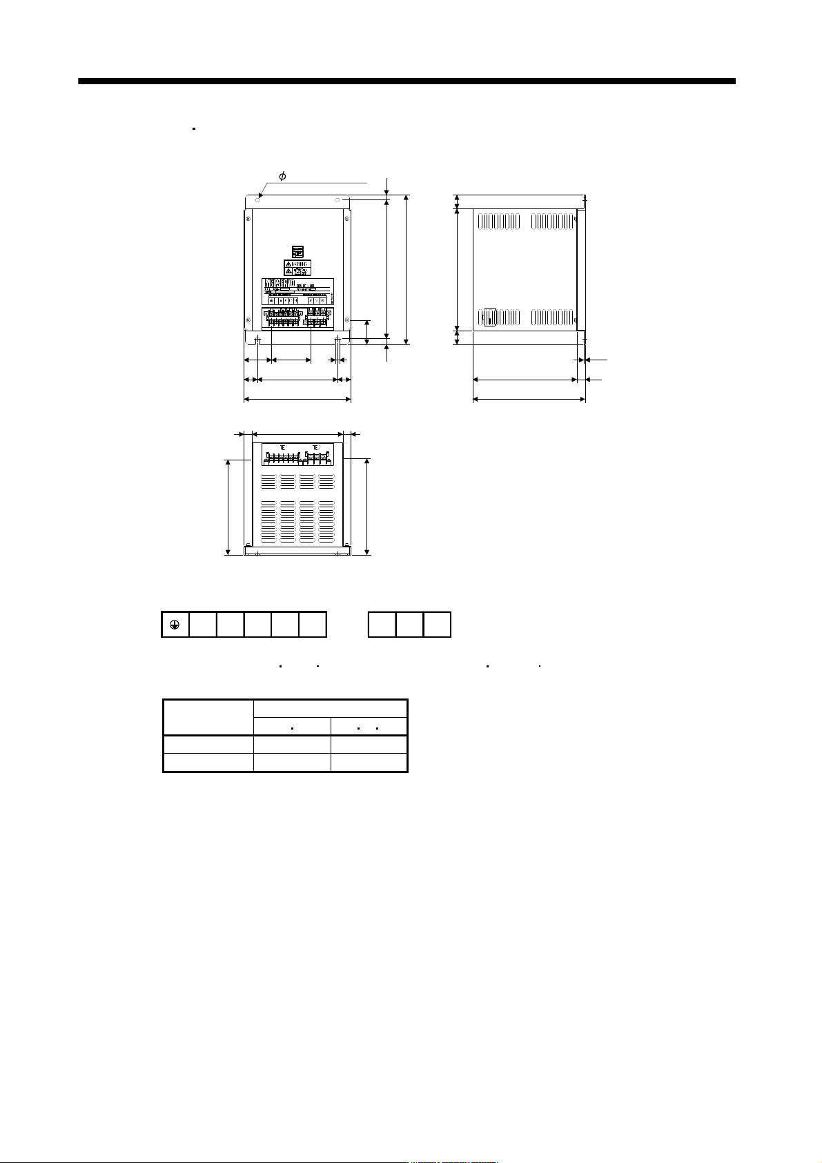
(b) DBU-11K-4
DBU-22K-4
[Unit: mm]
15
51
25
15
73.75 7
25150
10
200
170
178.5
179.5
15
260
280
43
10
2- 7mounting hole
195
228
2626
210
2.3
Mass: 6.7[kg]
a
TE1
Tightening torque: 0.8[N m](7[lb in])
Screw: M3.5
b 13 14
Terminal block
WVU
Tightening torque: 1.2[N m](10.6[lb in])
Screw: M4
TE2
Dynamic brake
Wire [mm
2
] (Note)
a b U V W
DBU-11K 2 5.5
DBU-15K, 22K 2 5.5
Note. Selection condition of wire size is as follows.
Wire type: 600V Polyvinyl chloride insulated wire (IV wire)
Construction condition: One wire is constructed in the air
11 - 61
11. OPTIONS AND AUXILIARY EQUIPMENT
11.7 Junction terminal block PS7DW-20V14B-F (recommended)
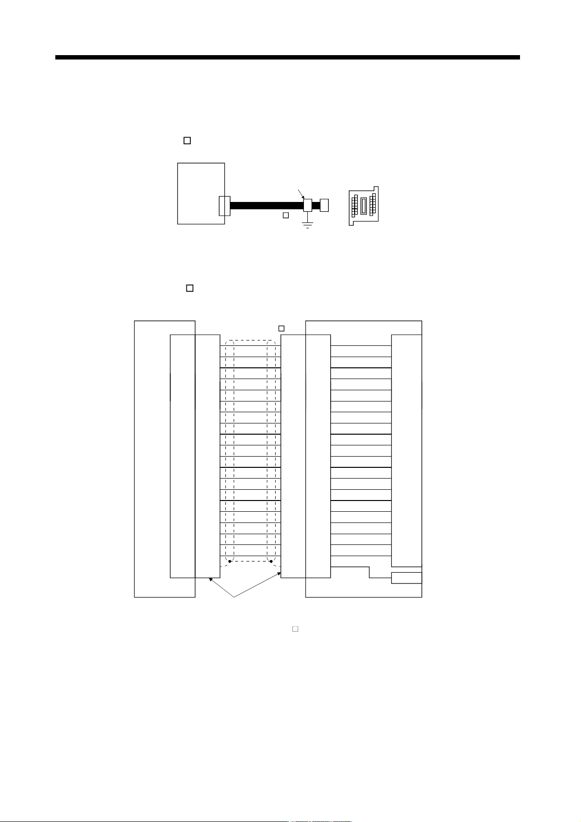
(1) How to use the junction terminal block
Always use the junction terminal block (PS7W-20V14B-F(YOSHIDA ELECTRIC INDUSTRY)) with the
option cable (MR-J2HBUS
M) as a set. A connection example is shown below.
Servo amplifier
Cable clamp
(AERSBAN-ESET)
Junction terminal block
PS7DW-20V14B-F
CN3
MR-J2HBUS M
Ground the option cable on the junction terminal block side with the cable clamp fitting (AERSBAN-ESET).
For the use of the cable clamp fitting, refer to section 11.14, (2)(c).
(2) Connection of MR-J2HBUS
M cable and junction terminal block
LG
DI1
1
2
DOC
MO1
3
4
LZ 8
LB 7
9
SD Shell
INP
5
6
10DICO
DICO
LA
LG
DI2
11
12
MBR
MO2
13
14
LZR 18
LBR 17
19DI3
15
16
20EM1
AMR
LAR
Shell Shell Shell
1
2
3
4
8
7
9
5
6
10
11
12
13
14
18
17
19
15
16
20
1
2
3
4
8
7
9
5
6
10
11
12
13
14
18
17
19
15
16
20
1
2
3
4
8
7
9
5
6
10
11
12
13
14
18
17
19
15
16
20
LG
DI1
DOC
MO1
LZ
LB
SD
INP
DICO
DICO
LA
LG
DI2
MBR
MO2
LZR
LBR
DI3
EM1
AMR
LAR
E
Servo amplifier
CN3
Junction terminal block
PS7W-20V14B-F
Connector: 10120-6000EL (3M)
Shell kit: 10320-3210-000 (3M)
CN
Terminal block
1
2
3
4
8
7
9
5
6
10
11
12
13
14
18
17
19
15
16
20
(Note)MR-J2HBUS M
Note. Symbol indicating cable length is put in .
05: 0.5m
1: 1m
5: 5m