sh030051g.pdf - 第312页
13 - 11 13. SERVO AMPLIFIERS WI TH A LARGE CAPACITY ( 30k TO 55kW ) (2) Drive unit (MR-J3-DU30KB4 MR-J3-DU37KB4) POINT The servo amplifier is shown with the fro nt cover opened. For removal of the front cover, refer to s…
13 - 10
13. SERVO AMPLIFIERS WITH A LARGE CAPACITY
(
30k TO 55kW
)
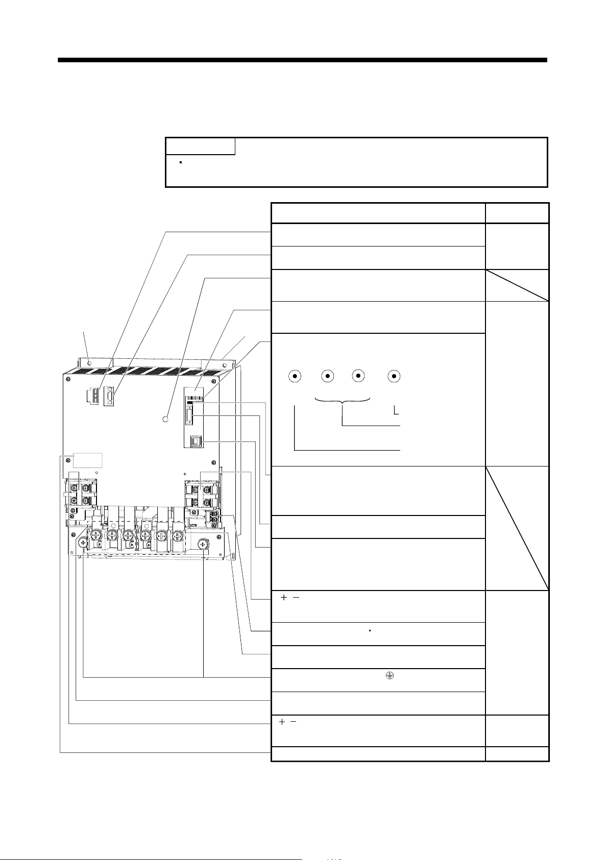
13.1.6 Parts identification
(1) Converter unit (MR-J3-CR55K(4))
POINT
The servo amplifier is shown without the front cover. For removal of the front
cover, refer to section 13.1.7.
Protective earth (PE) terminal ( )
Ground terminal.
L L terminal (TE2-1)
When using brake unit, connect it to this terminal. Do not
connect anything other than the brake unit.
Section 13.3.4
Name/Application
Detailed
explanation
I/O signal connector (CN1)
Used to connect digital I/O signals.
Main circuit terminal block (TE1-1)
Supply main circuit power.
Regenerative option Power factor improving DC reactor
(TE1-2)
Section 13.3.3
Charge lamp
Lit to indicate that the main circuit is charged. While
this lamp is lit, do not reconnect the cables.
L L terminal (TE2-2)
Used to connect to a drive unit using a connection
conductor supplied with drive unit.
Magnetic contactor control connector (CNP1)
Connect to the operation coil of the magnetic contactor.
Display
The 3-digit, seven-segment LED shows the servo status
and alarm number.
For manufacturer setting connector (CN6)
The connector is for manufacturer setting. Although the
shape is similar to analog monitor connector (CN6) of the
drive unit, do not connect anything including an analog
monitor.
Protection coordination connector (CN40)
Connect to CN40A of the drive unit.
Operation section
Used to perform status display, diagnostic, alarm,
parameter and point table setting operations.
MODE UP
DOWN
SET
Section 13.4
For manufacturer setting connector (CN3)
For manufacturer adjustment. Though the shape is similar
to RS-422 communication connector (CN3), do not
connect anything, including a personal computer and MR-
PRU03 parameter unit.
Fixed part
(4 places)
Cooling fan
Used to set data.
Used to change the
display or data in each
mode.
Used to change the
mode.
Control circuit terminal L
11
L
21
(TE3)
Supply control circuit power.
Section 13.1.4
Rating plate
Section 13.9.10
13 - 11
13. SERVO AMPLIFIERS WITH A LARGE CAPACITY
(
30k TO 55kW
)
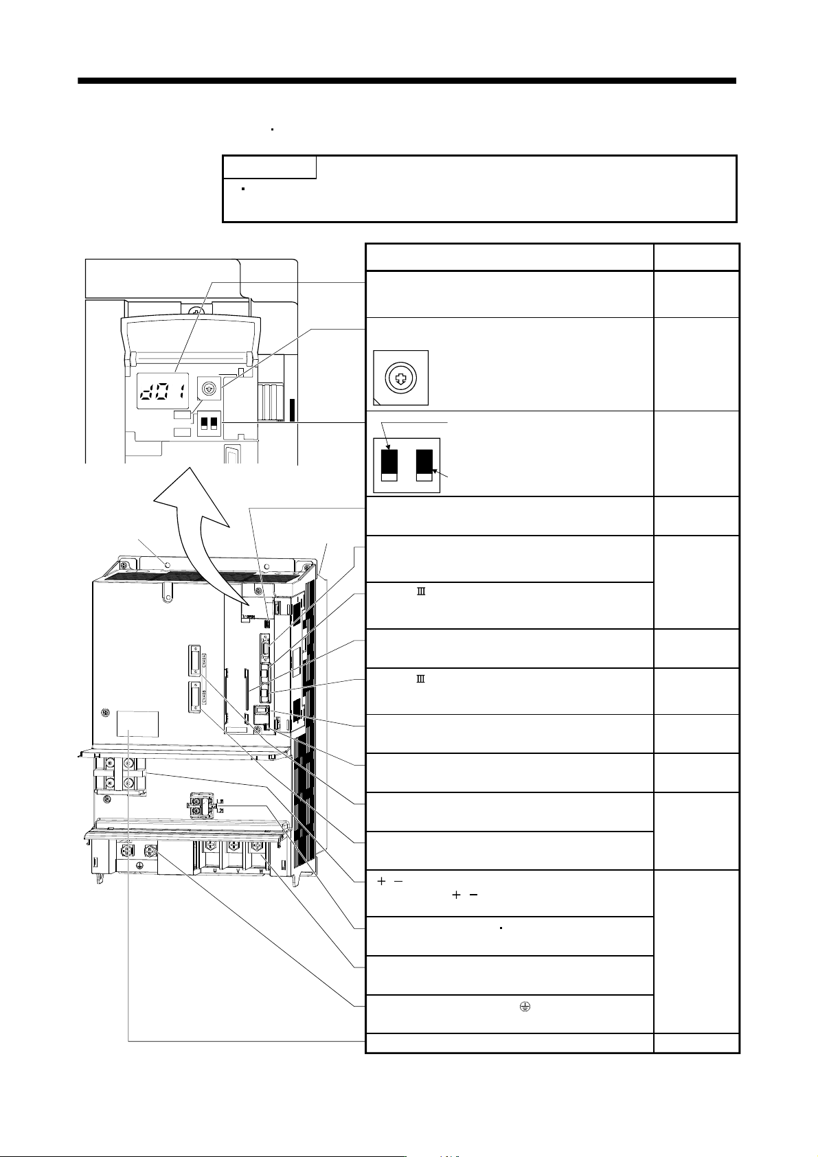
(2) Drive unit (MR-J3-DU30KB4
MR-J3-DU37KB4)
POINT
The servo amplifier is shown with the front cover opened. For removal of the
front cover, refer to section 13.1.7.
7
9
6
8
5
4
3
2
1
0
F
E
D
C
B
A
12
ON 4F
SW1
SW2
TEST
Cooling fan
Chapter 4
Section 3.2
Section 3.4
Section 11.8
Section 3.13
Section 3.13
Section 13.1.4
Section 3.4
Section 11.1
Section 11.9
Chapter 12
Section 3.2
Section 3.4
Section 12.3
Test operation select switch (SW2-1)
Used to perform the test operation mode
by using MR Configurator.
Spare (Be sure to set to the "Down"
position).
Rating plate
Section 13.3.2
SW2
SW1
8
7
6
5
4
3
2
1
0
F
E
D
C
B
A
9
12
Section 13.3.3
L L terminals (TE2)
Connect to the L L terminals of the converter unit
using the connection conductors supplied.
Control circuit terminal L11 L21 (TE3)
Supply control circuit power.
Motor power supply terminals (TE1)
Connect to U, V, W of the servo motor.
Display
The 3-digit, seven-segment LED shows the servo
status and alarm number.
Used to set the axis No. of drive unit.
Rotary axis setting switch (SW1)
USB communication connector (CN5)
Connect with the personal computer.
Battery holder
Contains the battery for absolute position data backup.
Encoder connector (CN2)
Used to connect the servo motor encoder.
SSCNET cable connector (CN1B)
Used to connect the rear axis drive unit. For the final axis,
puts a cap.
I/O signal connector (CN3)
Used to connect digital I/O signals.
More over an analog monitor is output
SSCNET cable connector (CN1A)
Used to connect the servo system controller or the front
axis drive unit.
Converter unit connectors (CN40A)
Connect to CN40 of the converter unit.
Battery connector (CN4)
Used to connect the battery for absolute position data
Converter unit connectors (CN40B)
Connect the termination connector (MR-J3-TM).
Fixed part
(4 places)
Name/Application
Detailed
explanation
Protective earth (PE) terminal ( )
Ground terminal.
13 - 12
13. SERVO AMPLIFIERS WITH A LARGE CAPACITY
(
30k TO 55kW
)
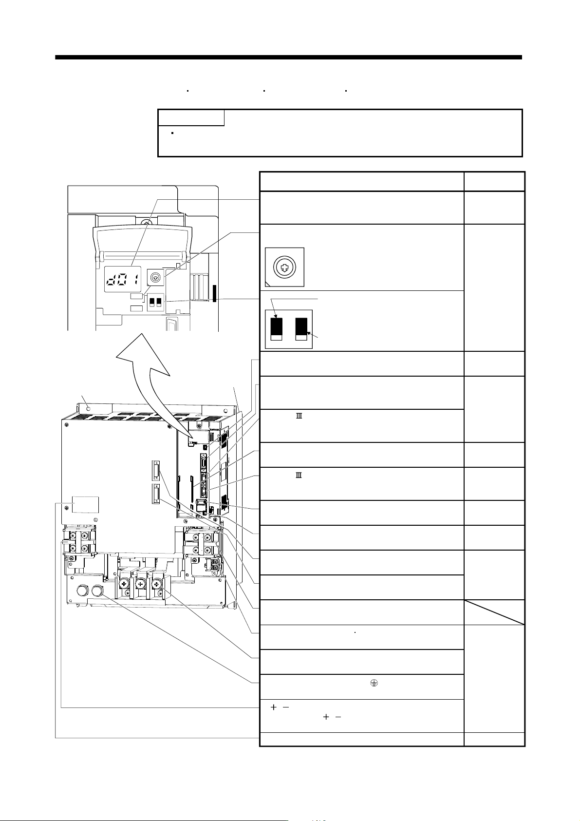
(3) Drive unit (MR-J3-DU30KB
MR-J3-DU37KB MR-J3-DU45KB4 MR-J3-DU55KB4)
POINT
This servo amplifier is shown without the front cover. For removal of the front
cover, refer to section 13.1.7.
7
9
6
8
5
4
3
2
1
0
F
E
D
C
B
A
12
ON 4F
SW1
SW2
TEST
fixed part
(4 places)
Cooling fan
Chapter 4
Section 3.2
Section 3.4
Section 11.8
Section 3.13
Section 13.1.4
Section 3.4
Section 11.1
Section 11.9
Chapter 12
Section 3.2
Section 3.4
Section 12.3
Rating plate
Section 13.3.2
SW2
SW1
8
7
6
5
4
3
2
1
0
F
E
D
C
B
A
9
12
Section 13.3.3
Motor power supply terminals (TE1)
Connect to U, V, W of the servo motor.
Display
The 3-digit, seven-segment LED shows the servo
status and alarm number.
Used to set the axis No. of drive unit.
Rotary axis setting switch (SW1)
USB communication connector (CN5)
Connect with the personal computer.
Battery holder
Contains the battery for absolute position data backup.
Encoder connector (CN2)
Used to connect the servo motor encoder.
SSCNET cable connector (CN1B)
Used to connect the rear axis drive unit. For the final axis,
puts a cap.
I/O signal connector (CN3)
Used to connect digital I/O signals.
More over an analog monitor is output
SSCNET cable connector (CN1A)
Used to connect the servo system controller or the front
axis drive unit.
Converter unit connectors (CN40A)
Connect to CN40 of the converter unit.
Battery connector (CN4)
Used to connect the battery for absolute position data
Converter unit connectors (CN40B)
Connect the termination connector (MR-J3-TM).
Name/Application
Detailed
explanation
TE2-2
For manufacturer adjustment. Leave this open.
Control circuit terminal L
11
L
21
(TE3)
Supply control circuit power.
L L terminals (TE2)
Connect to the L L terminals of the converter unit
using the connection conductors supplied.
Test operation select switch (SW2-1)
Used to perform the test operation mode
by using MR Configurator.
Spare (Be sure to set to the "Down"
position).
Protective earth (PE) terminal ( )
Ground terminal.