sh030051g.pdf - 第230页
11 - 25 11. OPTIONS AND AUXILI ARY EQUIPMENT (a) MR-J3-350B or less MR-J3-200B4 or less Always remove the wiring fr om across P- D and fit the regenerative o ption across P-C. The G3 and G4 terminals act as a ther mal se…
11 - 24
11. OPTIONS AND AUXILIARY EQUIPMENT
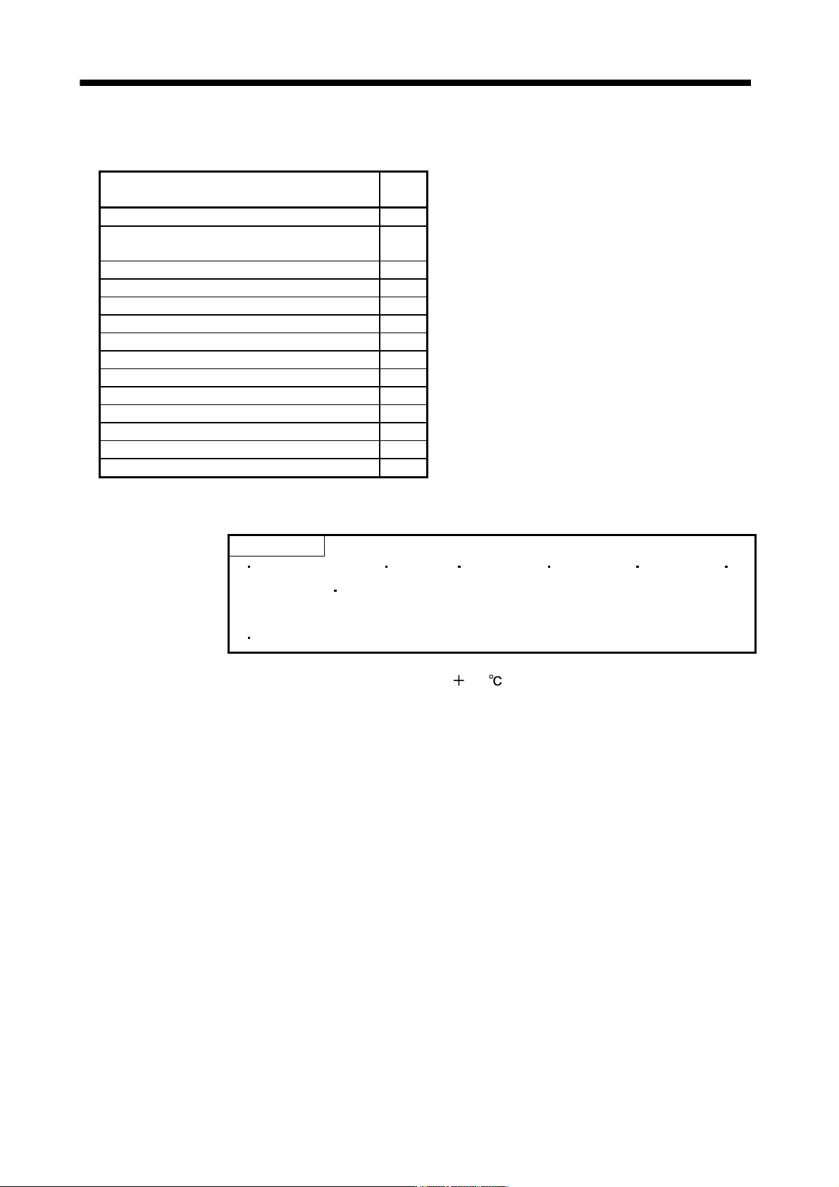
The following are setting values for regenerative resistor and regenerative option which are used with a
servo amplifier of 11k to 22kW.
Regenerative resistor, regenerative option
Setting
value
Standard supplied regenerative resistor 00
Standard supplied regenerative resistor
(with a cooling fan to cool it)
FA
MR-RB5E 00
MR-RB5E (with a cooling fan to cool it) FA
MR-RB9P 00
MR-RB9P (with a cooling fan to cool it) FA
MR-RB9F 00
MR-RB9F (with a cooling fan to cool it) FA
MR-RB6B-4 00
MR-RB6B-4 (with a cooling fan to cool it) 00
MR-RB60-4 FA
MR-RB60-4 (with a cooling fan to cool it) 00
MR-RB6K-4 FA
MR-RB6K-4 (with a cooling fan to cool it) 00
(4) Connection of the regenerative option
POINT
When the MR-RB50 MR-RB51 MR-RB3M-4 MR-RB3G-4 MR-RB5G-4
MR-RB34-4
MR-RB54-4 is used, a cooling fan is required to cool it.
The cooling fan should be prepared by the customer.
For the sizes of wires used for wiring, refer to section 11.11.
The regenerative option will cause a temperature rise of
100 relative to the ambient temperature. Fully
examine heat dissipation, installation position, used cables, etc. before installing the option. For wiring, use
flame-resistant wires and keep them clear of the regenerative option body. Always use twisted cables of
max. 5m length for connection with the servo amplifier.
11 - 25
11. OPTIONS AND AUXILIARY EQUIPMENT
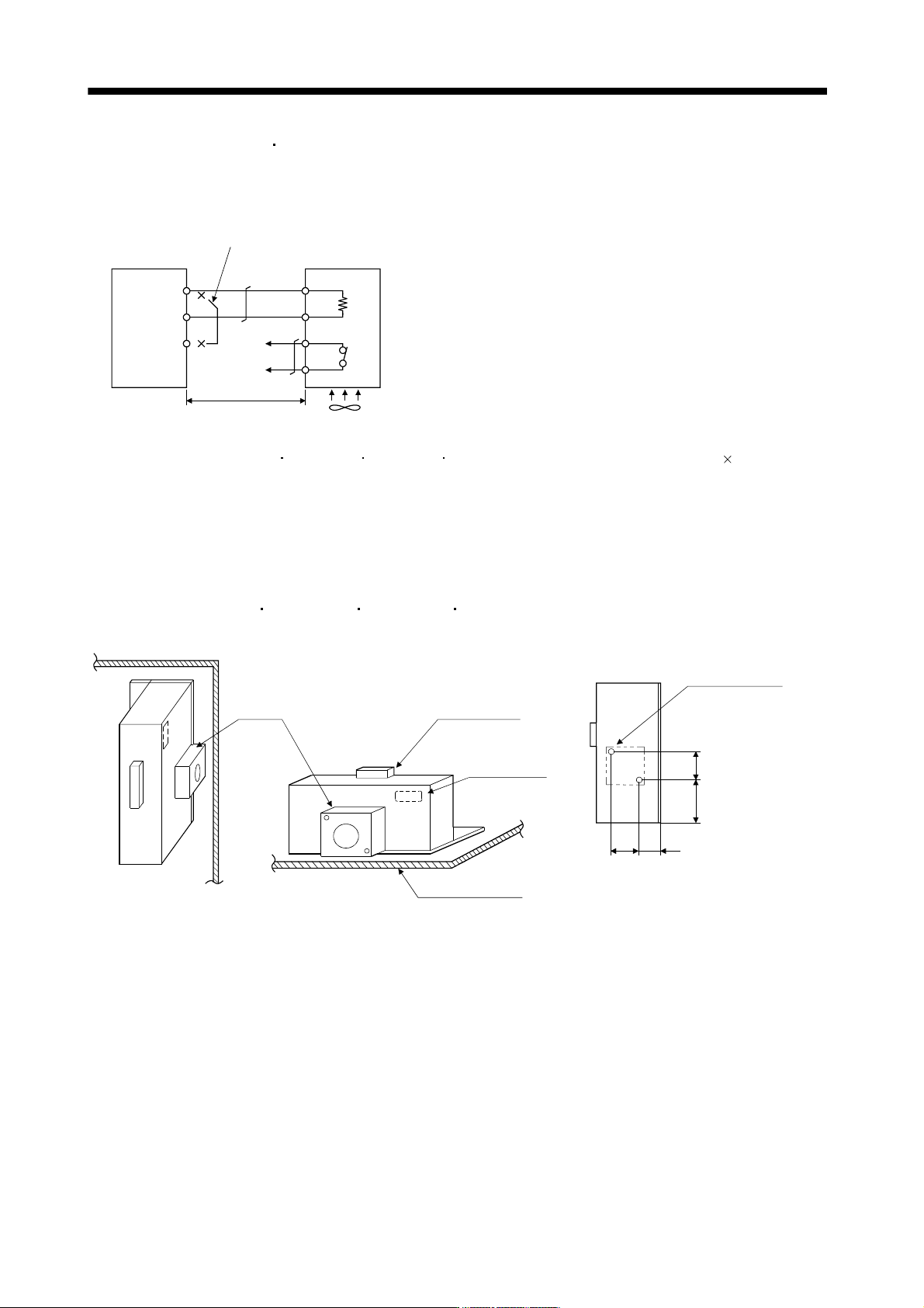
(a) MR-J3-350B or less
MR-J3-200B4 or less
Always remove the wiring from across P-D and fit the regenerative option across P-C.
The G3 and G4 terminals act as a thermal sensor. G3-G4 is disconnected when the regenerative option
overheats abnormally.
D
P
C
G4
G3
C
P
Regenerative option
5m max.
Servo amplifier
Always remove the lead from across P-D.
(Note 2)
Cooling fan
(Note 1)
Note 1. When using the MR-RB50 MR-RB3M-4 MR-RB3G-4 MR-RB5G-4, forcibly cool it with a cooling fan (92 92, minimum air
flow : 1.0m
3
).
2. Make up a sequence which will switch off the magnetic contactor (MC) when abnormal heating occurs.
G3-G4 contact specifications
Maximum voltage: 120V AC/DC
Maximum current: 0.5A/4.8VDC
Maximum capacity: 2.4VA
For the MR-RB50
MR-RB3M-4 MR-RB3G-4 MR-RB5G-4 install the cooling fan as shown.
(for cooling fan installation)
Depth 10 or less
(Screw hole already
machined)
Cooling fan installation screw hole dimensions
82.5
40
82.5
133
2-M3 screw hole
Terminal block
Thermal relay
Installation surface
Horizontal installation
Vertical
installation
Top
Bottom
[Unit : mm]
Cooling fan
11 - 26
11. OPTIONS AND AUXILIARY EQUIPMENT
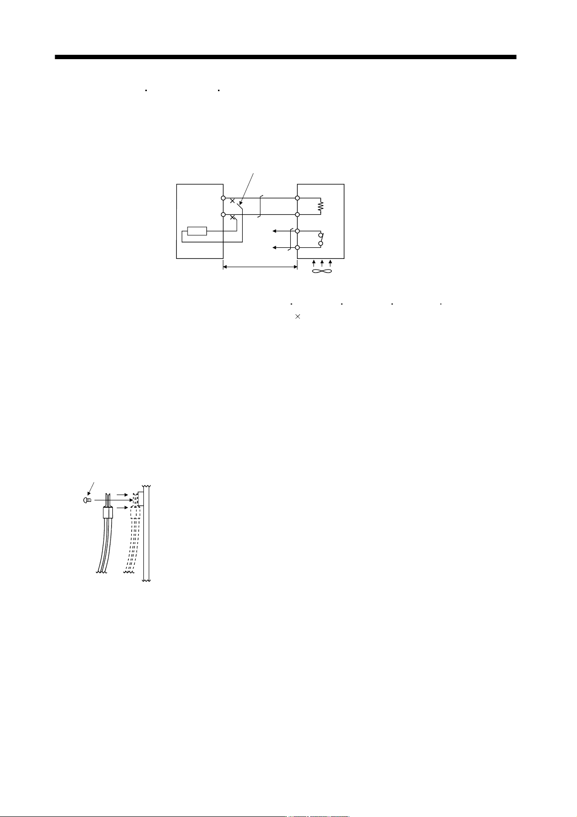
(b) MR-J3-350B4
MR-J3-500B(4) MR-J3-700B(4)
Always remove the wiring (across P-C) of the servo amplifier built-in regenerative resistor and fit the
regenerative option across P-C.
The G3 and G4 terminals act as a thermal sensor. G3-G4 is opened when the regenerative option
overheats abnormally.
Regenerative optionServo amplifier
Cooling fan(Note 1)
P
C
G4
G3
C
P
Always remove wiring (across P-C) of servo
amplifier built-in regenerative resistor.
5m or less
(Note 2)
Note 1. When using the MR-RB51 MR-RB3G-4 MR-RB5G-4 MR-RB34-4 MR-RB54-4, forcibly
cool it with a cooling fan (92
92, minimum air flow : 1.0m
3
).
2. Make up a sequence which will switch off the magnetic contactor (MC) when abnormal heating
occurs.
G3-G4 contact specifications
Maximum voltage: 120V AC/DC
Maximum current: 0.5A/4.8VDC
Maximum capacity: 2.4VA
When using the regenerative resistor option, remove the servo amplifier's built-in regenerative resistor
terminals (across P-C), fit them back to back, and secure them to the frame with the accessory screw as
shown below.
Mounting method
Accessory screw