sh030051g.pdf - 第244页
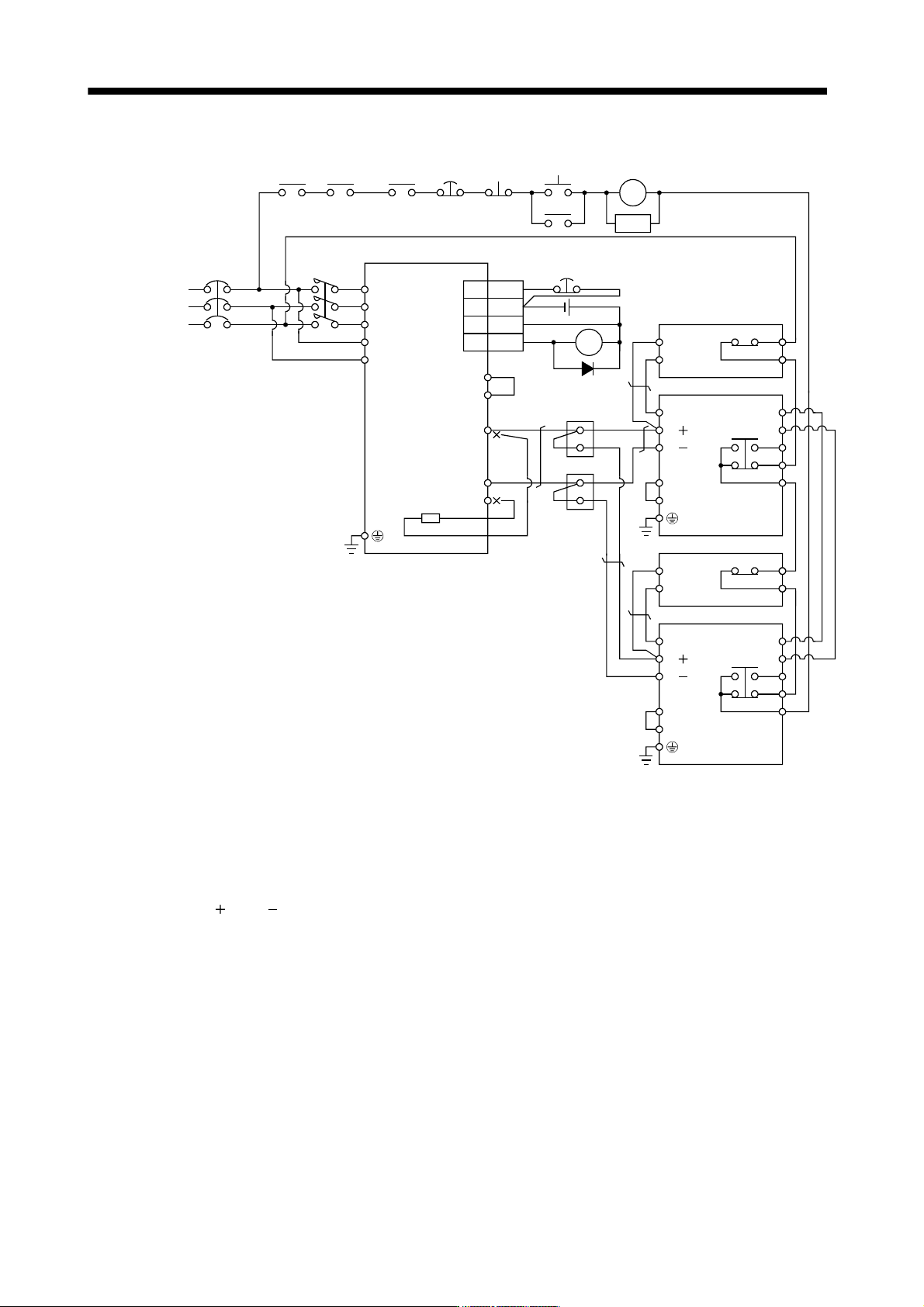
11 - 39 11. OPTIONS AND AUXILI ARY EQUIPMENT (2) Combination with MT-BR5-(H) resistor unit NFB 24VDC ALM RA1 MC SK MC ON OFF EM1 Servo motor therm al relay RA2 (Note 1) Power supply N/ P/ BUE SD PR B C A SD MSG (Not e 3)…
11 - 38
11. OPTIONS AND AUXILIARY EQUIPMENT
Controller
forced stop
RA3
NFB
24VDC
ALM
RA1
MC
SK
MC
ON
OFF
EM1
Servo motor
thermal relay
RA2
(Note 7)
(Note 1)
Power
supply
N/
P/
BUE
SD
PR
B
C
A
SD
MSG
(Note 4)
(Note 6)
3
10
EM1
DOCOM
DICOM
ALM
P
1
P
2
P
N
C
FR-BU2-(H)
FR-BR
Servo amplifier
P
PR
TH2
TH1
(Note 5)
MC
Terminal
block
(Note 3)
(Note 11)
(Note 2)
(Note 8)
20
15
CN3
L
1
L
2
L
3
L
11
L
21
(Note 10)
(Note 9)
N/
P/
BUE
SD
PR
B
C
A
SD
MSG
FR-BU2-(H)
TH2
TH1
(Note 5)
FR-BR
P
PR
RA1
(Note 4)
(Note 6)
(Note 10)
(Note 9)
Note 1. For power supply specifications, refer to section 1.3.
2. For the servo amplifier of 5k and 7kW, always disconnect the lead of built-in regenerative resistor, which is connected to the P
and C terminals. For the servo amplifier of 11k and 15kW, do not connect a supplied regenerative resistor to the P and C
terminals.
3. Always connect P
1 and P2 terminals (P1 and P for the servo amplifier of 11k and 15kW) (Factory-wired). When using the power
factor improving DC reactor, refer to section 11.13.
4. Connect the P/
and N/ terminals of the brake unit to a correct destination. Wrong connection results in servo amplifier and
brake unit malfunction.
5. Contact rating: 1b contact, 110VAC_5A/220VAC_3A
Normal condition: TH1-TH2 is conducting. Abnormal condition: TH1-TH2 is not conducting.
6. Contact rating: 230VAC_0.3A/30VDC_0.3A
Normal condition: B-C is conducting/A-C is not conducting. Abnormal condition: B-C is not conducting/A-C is conducting.
7. For the servo amplifier of 11kW or more, connect the thermal relay censor of the servo amplifier.
8. Do not connect more than one cable to each P and N terminals of the servo amplifier.
9. Always connect BUE and SD terminals (Factory-wired).
10. Connect the MSG and SD terminals of the brake unit to a correct destination. Wrong connection results in servo amplifier and
brake unit malfunction.
11. For the cable to connect the terminal block and the P and N terminals of the servo amplifier, use the cable indicated in (4) (b) of
this section.
11 - 39
11. OPTIONS AND AUXILIARY EQUIPMENT
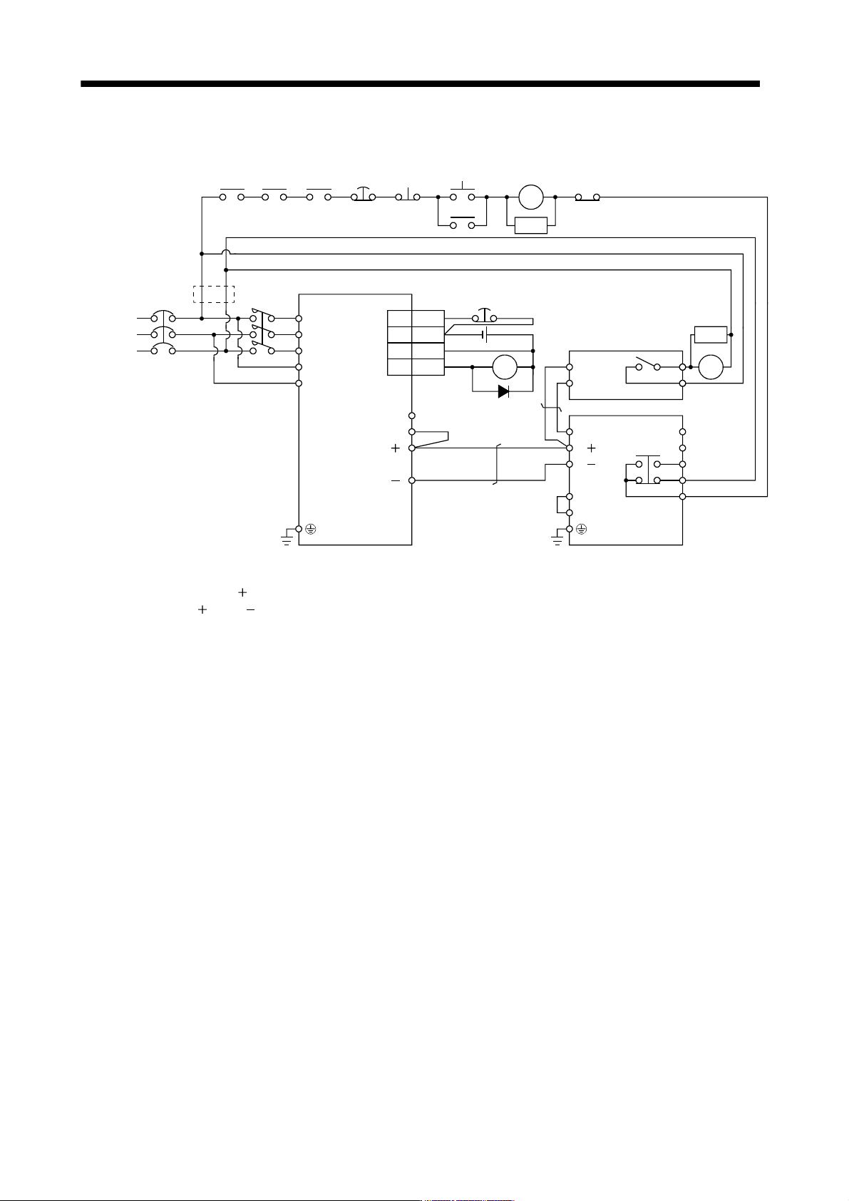
(2) Combination with MT-BR5-(H) resistor unit
NFB
24VDC
ALM
RA1
MC
SK
MC
ON
OFF
EM1
Servo motor
thermal relay
RA2
(Note 1)
Power
supply
N/
P/
BUE
SD
PR
B
C
A
SD
MSG
(Note 3)
(Note 6)
RA4
3
10
EM1
DOCOM
DICOM
ALM
P
1
P( )
N( )
FR-BU2-(H)
MT-BR5-(H)
Servo amplifier
P
PR
TH2
TH1
(Note 5)
MC
(Note 4)
RA4
(Note 7)
(Note 2)
20
15
CN3
L
3
L11
L
2
L21
L
1
SK
(Note 8)
RA1
Controller
forced stop
RA3
C
(Note 9)
Note 1. For power supply specifications, refer to section 1.3.
2. Always connect P
1 - P( ) terminals (Factory-wired). When using the power factor improving DC reactor, refer to section 11.13.
3. Connect the P/
and N/ terminals of the brake unit to a correct destination. Wrong connection results in servo amplifier and
brake unit malfunction.
4. For the servo amplifier of 400V class, a step-down transformer is required.
5. Contact rating: 1a contact, 110VAC_5A/220VAC_3A
Normal condition: TH1-TH2 is not conducting. Abnormal condition: TH1-TH2 is conducting.
6. Contact rating: 230VAC_0.3A/30VDC_0.3A
Normal condition: B-C is conducting/A-C is not conducting. Abnormal condition: B-C is not conducting/A-C is conducting.
7. Do not connect more than one cable to each P and N terminals of the servo amplifier.
8. Always connect BUE and SD terminals (Factory-wired).
9. For the servo amplifier of 22kW, do not connect a supplied regenerative resistor to the P and C terminals.
11 - 40
11. OPTIONS AND AUXILIARY EQUIPMENT
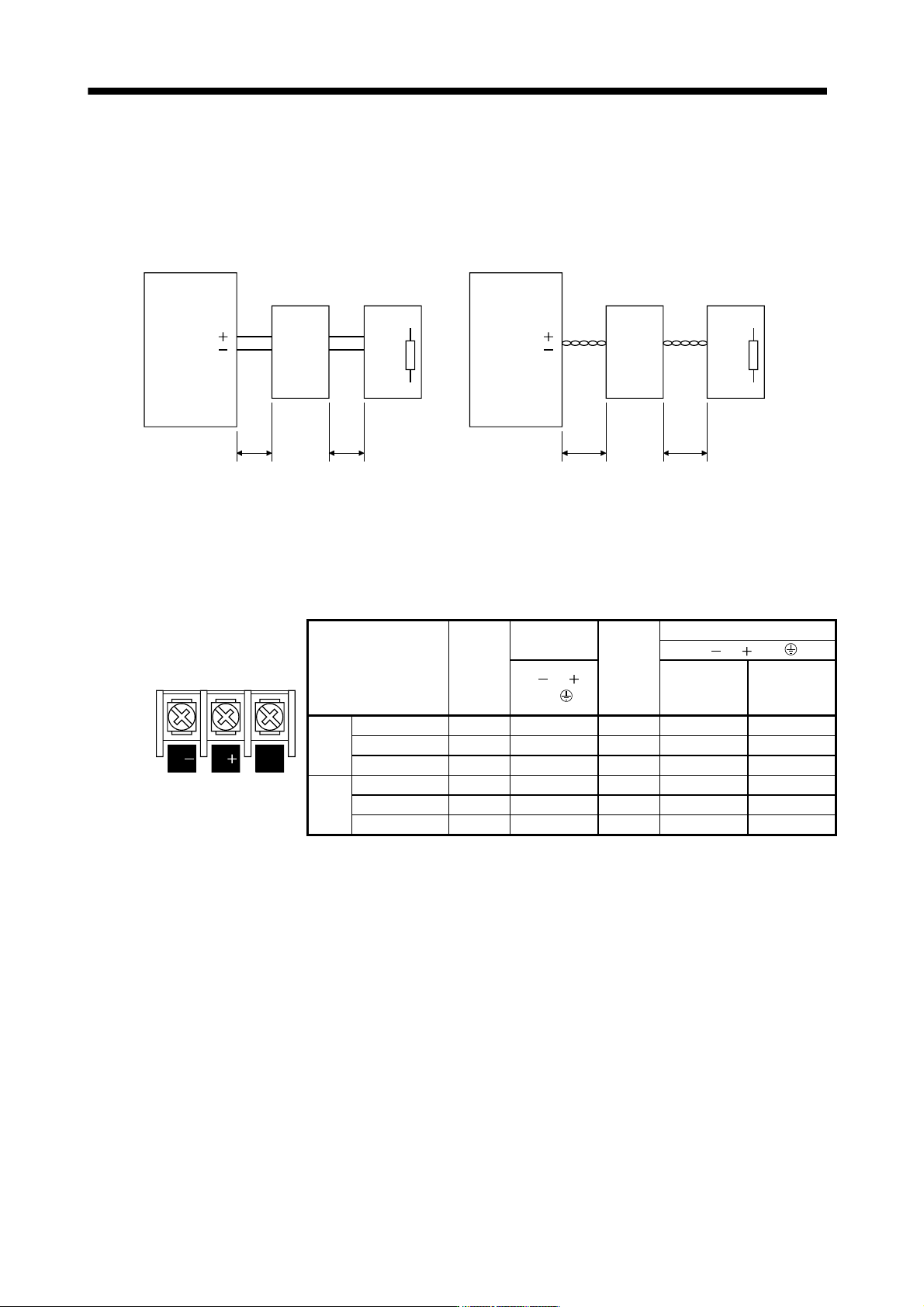
(3) Precautions for wiring
The cables between the servo amplifier and the brake unit, and between the resistor unit and the brake unit
should be as short as possible. Always twist the cable longer than 5m (twist five times or more per one
meter). Even when the cable is twisted, the cable should be less than 10m. Using cables longer than 5m
without twisting or twisted cables longer than 10m, may result in the brake unit malfunction.
Servo amplifier
Brake unit
5m or less 5m or less
Servo amplifier
Brake unit
10m or less 10m or less
P( )
N( )
P
N
P
PR
PR
P
N
P
PR
P
PR
Twist
Resistor unit Resistor unit
P( )
N( )
Twist
P
(4) Cables
(a) Cables for the brake unit
For the brake unit, HIV wire (600V Grade heat-resistant polyvinyl chloride insulated wire) is
recommended.
1) Main circuit terminal
Brake unit
Main
circuit
terminal
screw
size
Crimping
terminal
Tightening
torque
Wire size
N/
, P/ , PR,
N/ P/ PR
Terminal block
N/ , P/ ,
PR,
HIV wire [mm
2
] AWG
200V FR-BU2-15K M4 5.5-4 1.5 3.5 12
class FR-BU2-30K M5 5.5-5 2.5 5.5 10
FR-BU2-55K M6 14-6 4.4 14 6
400V FR-BU2-H30K M4 5.5-4 1.5 3.5 12
class FR-BU2-H55K M5 5.5-5 2.5 5.5 10
FR-BU2-H75K M6 14-6 4.4 14 6