sh030051g.pdf - 第85页
3 - 30 3. SIGNALS AND WI RING (3) Encoder output pulse DO-2 (D ifferential line driver system) (a) Interface Max. output current: 35mA LA (LB, LZ) LAR (LBR, L ZR) LG SD LA (LB, LZ) LAR (LBR, LZR) SD Servo amplifier Servo…
3 - 29
3. SIGNALS AND WIRING
3.7.2 Detailed description of interfaces
This section provides the details of the I/O signal interfaces (refer to the I/O division in the table) given in
section 3.5. Refer to this section and make connection with the external equipment.
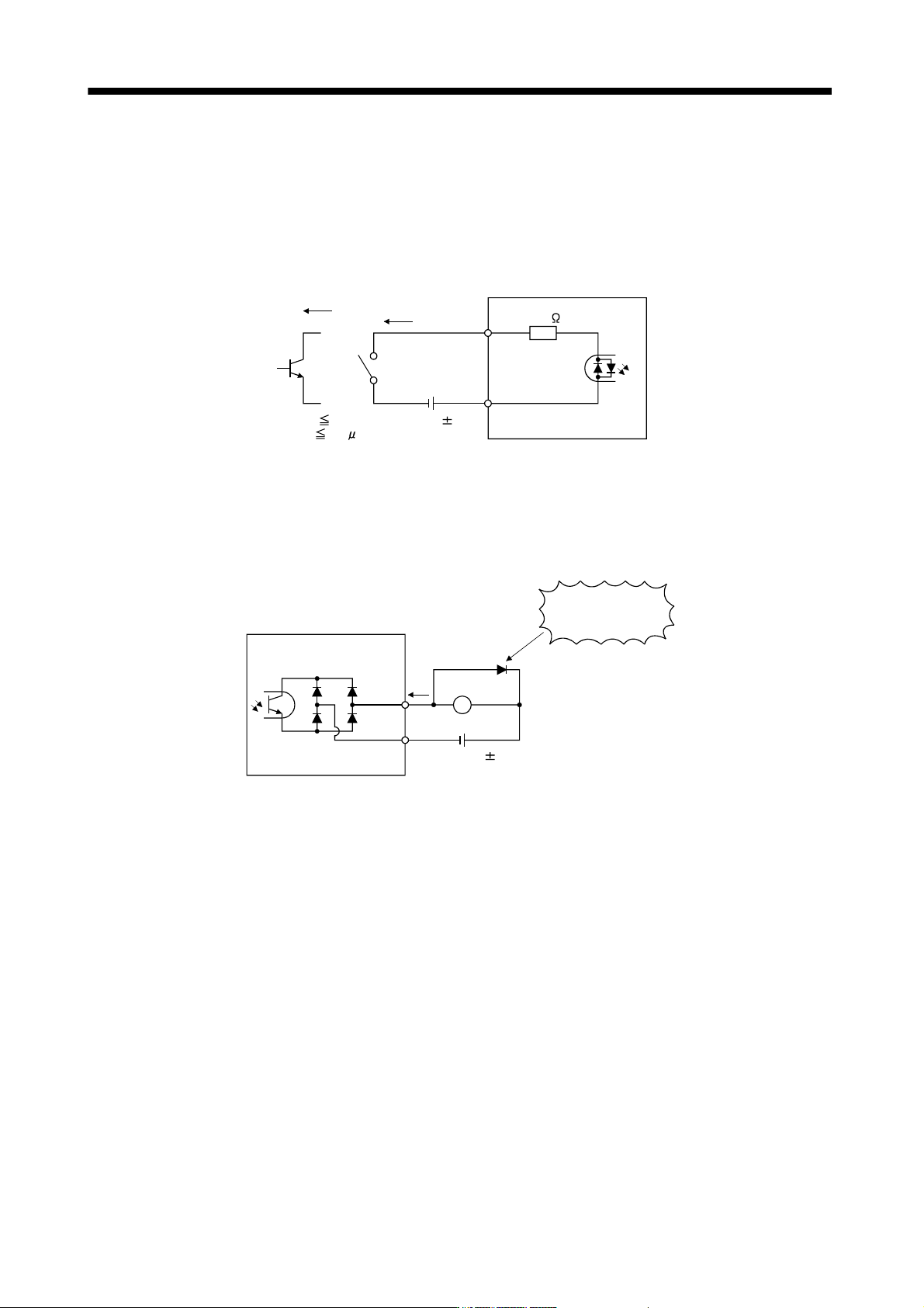
(1) Digital input interface DI-1
Give a signal with a relay or open collector transistor. Refer to section 3.7.3 for the source input.
DICOM
V
CES 1.0V
I
CEO
100
A
TR
24VDC 10%
5.6k
For transistor
Approx. 5mA
Switch
150mA
Servo amplifier
EM1,
etc.
(2) Digital output interface DO-1
A lamp, relay or photocoupler can be driven. Install a diode (D) for an inductive load, or install an inrush
current suppressing resistor (R) for a lamp load. (Rated current: 40mA or less, maximum current: 50mA or
less, inrush current: 100mA or less) A maximum of 2.6V voltage drop occurs in the servo amplifier.
Refer to section 3.7.3 for the source output.
If polarity of diode is
reversed, servo
amplifier will fail.
Servo amplifier
ALM,
etc.
Load
DOCOM
24VDC 10%
150mA
(Note)
Note. If the voltage drop (maximum of 2.6V) interferes with the relay operation, apply high voltage (up to
26.4V) from external source.
3 - 30
3. SIGNALS AND WIRING
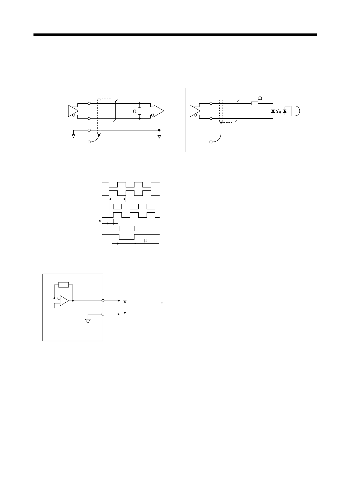
(3) Encoder output pulse DO-2 (Differential line driver system)
(a) Interface
Max. output current: 35mA
LA
(LB, LZ)
LAR
(LBR, LZR)
LG
SD
LA
(LB, LZ)
LAR
(LBR, LZR)
SD
Servo amplifier Servo amplifier
Am26LS32 or equivalent High-speed photocoupler
150
100
(b) Output pulse
Servo motor CCW rotation
LA
LAR
LB
LBR
LZ
LZR
T
/2
400 s or more
Time cycle (T) is determined by the settings
of parameter No.PA15 and PC03.
(4) Analog output
LG
MO1
Servo amplifier
Output voltage 10V
Max. 1mA
Max. Output current Resolution: 10 bi
t
(MO2)
3 - 31
3. SIGNALS AND WIRING
3.7.3 Source I/O interfaces
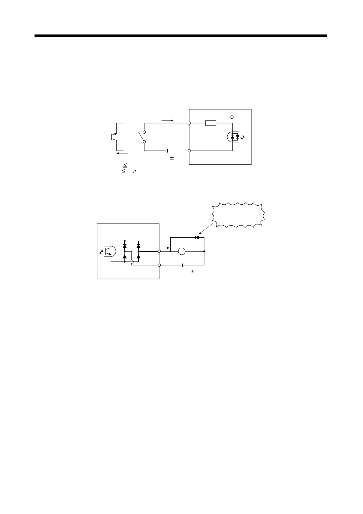
In this servo amplifier, source type I/O interfaces can be used. In this case, all DI-1 input signals and DO-1
output signals are of source type. Perform wiring according to the following interfaces.
(1) Digital input interface DI-1
EM1,
etc.
Servo amplifier
Switch
Approx. 5mA
DICOM
V
CES 1.0V
I
CEO
100
A
24VDC 10%
150mA
Approx. 5.6k
(2) Digital output interface DO-1
A maximum of 2.6V voltage drop occurs in the servo amplifier.
If polarity of diode is
reversed, servo
amplifier will fail.
Servo amplifier
ALM,
etc.
Load
DOCOM
24VDC 10%
150mA
(Note)
Note. If the voltage drop (maximum of 2.6V) interferes with the relay operation, apply high voltage (up to
26.4V) from external source.