sh030051g.pdf - 第111页
4 - 4 4. STARTUP 4.2 Start up Connect the servo motor with a machine after confir ming tha t the servo motor ope rates properly alone. (1) Power on When the main and control circuit power supplies are switched on, "…
4 - 3
4. STARTUP
2) When regenerative option is used over 5kW for 200V class and 3.5kW for 400V class
The lead of built-in regenerative resistor connected to P terminal and C terminal of TE1 terminal block
should not be connected.
The generative brake option should be connected to P terminal and C terminal.
A twisted cable should be used when wiring is over 5m and under 10m. (Refer to section 11.2)
3) When brake unit and power regenerative converter are used over 5kW
The lead of built-in regenerative resistor connected to P terminal and C terminal of TE1 terminal block
should not be connected.
Brake unit, power regenerative converter or power regeneration converter should be connected to P
terminal and N terminal. (Refer to section 11.3 to 11.5)
4) The power factor improving DC reactor should be connected P
1 and P2 (For 11k to 22kW, P
1
and P).
(Refer to section 11.13.)
P1
P2
Servo amplifie
r
(Note)
Power factor
improving DC
reactor
Note. Always disconnect P1 and P2. (For 11k to 22kW P1 and P)
(2) I/O signal wiring
(a) The I/O signals should be connected correctly.
Use DO forced output to forcibly turn on/off the pins of the CN3 connector. This function can be used to
perform a wiring check. In this case, switch on the control circuit power supply only.
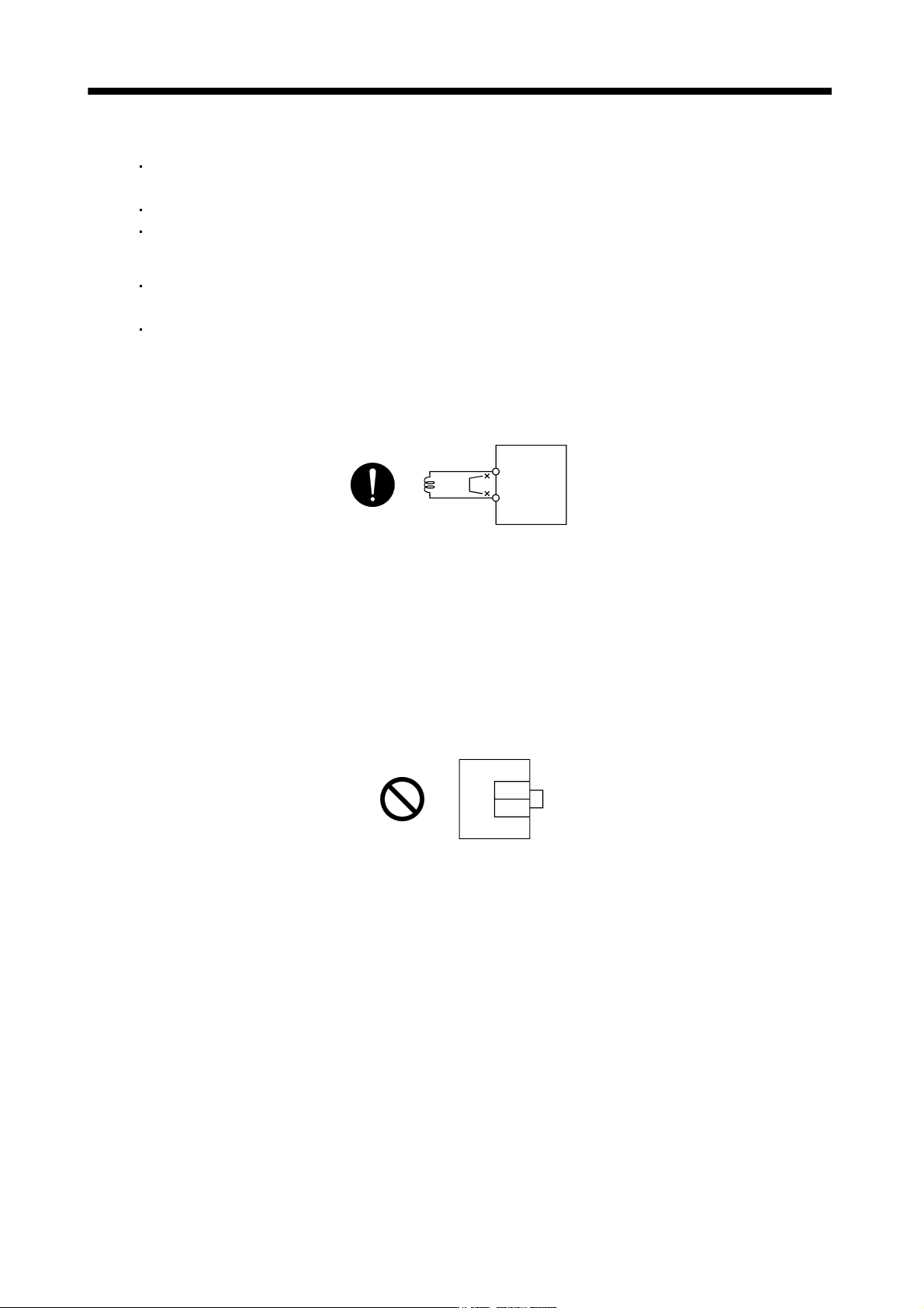
(b) 24VDC or higher voltage is not applied to the pins of connectors CN3.
(c) SD and DOCOM of connector CN3 is not shorted.
DOCOM
SD
CN3
Servo amplifier
4.1.3 Surrounding environment
(1) Cable routing
(a) The wiring cables are free from excessive force.
(b) The encoder cable should not be used in excess of its flex life. (Refer to section 10.4.)
(c) The connector part of the servo motor should not be strained.
(2) Environment
Signal cables and power cables are not shorted by wire offcuts, metallic dust or the like.
4 - 4
4. STARTUP
4.2 Start up
Connect the servo motor with a machine after confirming that the servo motor operates properly alone.
(1) Power on
When the main and control circuit power supplies are switched on, "b01" (for the first axis) appears on the
servo amplifier display.
In the absolute position detection system, first power-on results in the absolute position lost (25) alarm and
the servo system cannot be switched on.
The alarm can be deactivated by then switching power off once and on again.
Also in the absolute position detection system, if power is switched on at the servo motor speed of 500r/min
or higher, position mismatch may occur due to external force or the like. Power must therefore be switched
on when the servo motor is at a stop.
(2) Parameter setting
Set the parameters according to the structure and specifications of the machine. Refer to chapter 5 for the
parameter definitions.
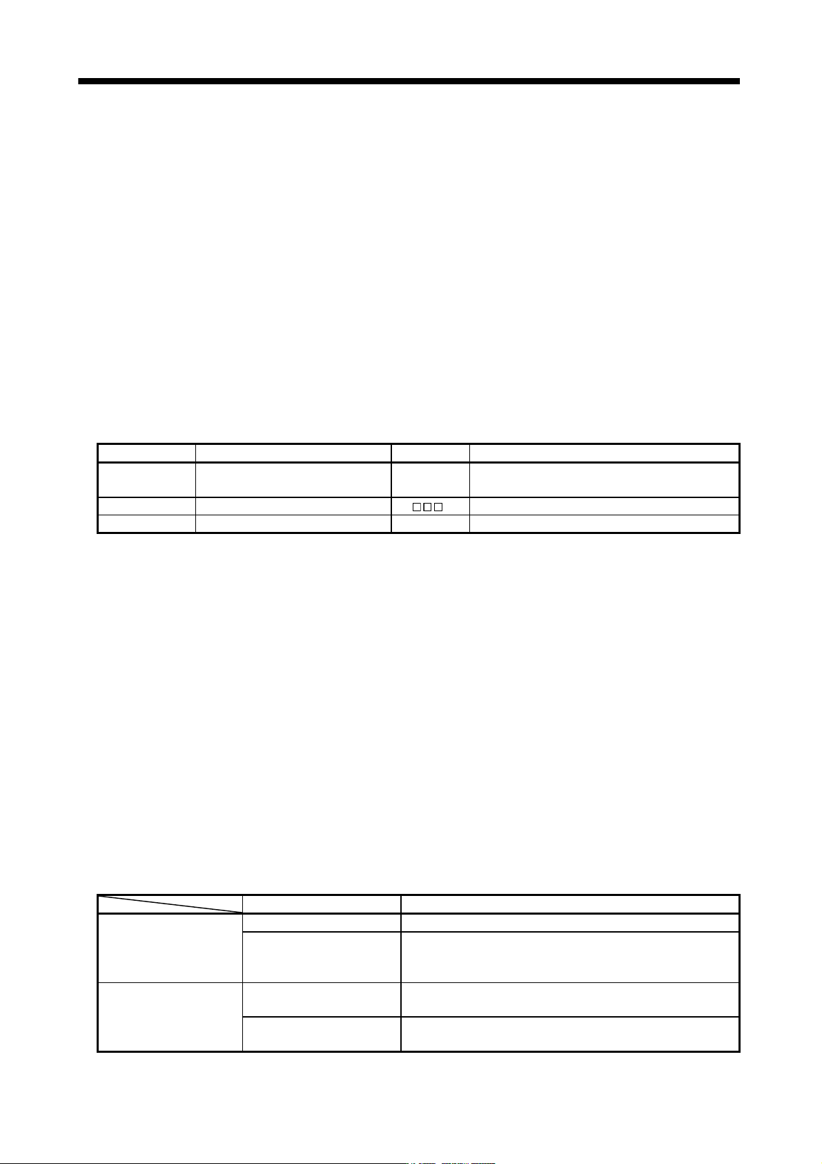
Parameter No. Name Setting Description
PA14 Rotation direction setting 0
Increase in positioning address rotates the motor in
the CCW direction.
PA08 Auto tuning mode 1 Used.
PA09 Auto tuning response 12 Slow response (initial value) is selected.
After setting the above parameters, switch power off once. Then switch power on again to make the set
parameter values valid.
(3) Servo-on
Switch the servo-on in the following procedure.
1) Switch on main circuit/control circuit power supply.
2) The controller transmits the servo-on command.
When placed in the servo-on status, the servo amplifier is ready to operate and the servo motor is locked.
(4) Home position return
Always perform home position return before starting positioning operation.
(5) Stop
If any of the following situations occurs, the servo amplifier suspends the running of the servo motor and
brings it to a stop.
When the servo motor is with an electromagnetic brake, refer to section 3.11.
Operation/command Stopping condition
Servo system controller
Servo off command The base circuit is shut off and the servo motor coasts.
Forced stop command
The base circuit is shut off and the dynamic brake operates to bring
the servo motor to stop. The controller forced stop warning (E7)
occurs.
Servo amplifier
Alarm occurrence
The base circuit is shut off and the dynamic brake operates to bring
the servo motor to stop.
Forced stop
(EM1) OFF
The base circuit is shut off and the dynamic brake operates to bring
the servo motor to stop. The servo forced stop warning (E6) occurs.
4 - 5
4. STARTUP
4.3 Servo amplifier display
On the servo amplifier display (three-digit, seven-segment display), check the status of communication with the
servo system controller at power-on, check the axis number, and diagnose a fault at occurrence of an alarm.
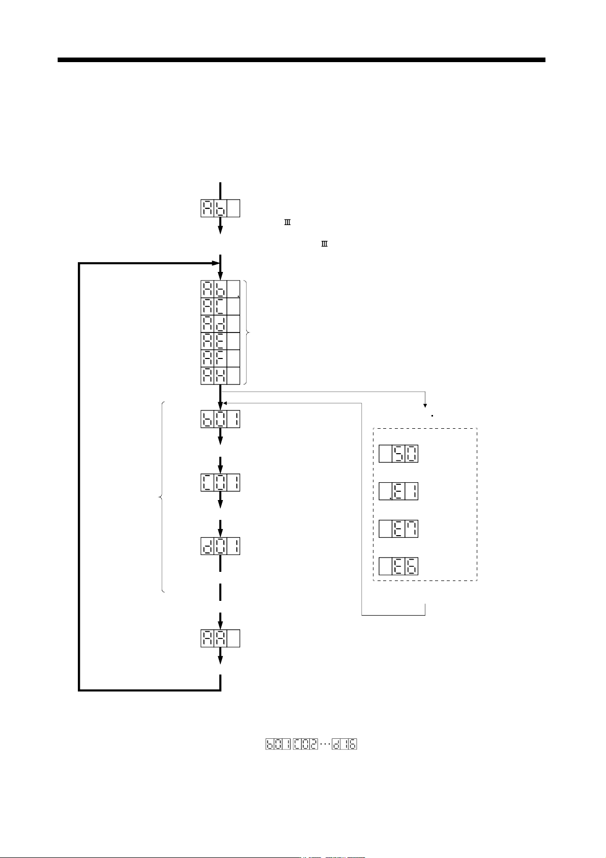
(1) Display sequence
Only alarm and warning No. are displayed, but no axis No. is displayed
Servo amplifier power ON
(Note 3)
At occurrence of overload
At occurrence of overload
warning (Note 2)
During controller
forced stop
During forced stop
Flicker
display
Alarm reset or
warning
1 axis 2 axis 16 axis
(Note 3)
(Note 3)
(Note 1)
When alarm warning
No. is displayed
Flicker
display
Flicker
display
Flicker
display
If warning other than E6 or E7 occurs during the servo on, flickering the
second place of decimal point indicates that it is during the servo on.
Note 1.
2.
3.
The right-hand segments of b01, c02 and d16 indicate the axis number.
(Below example indicates Axis1)
Initial data communication
with servo system controller
(Initialization communication)
When alarm occurs,
alarm code appears.
Ready ON
Ready OFF/servo OFF
Ready ON/servo OFF
Servo ON
Ready ON/servo ON
Servo system controller power ON
Ordinary operation
Servo system controller power OFF
Waiting for servo system controller
power to switch ON
(SSCNET communication)
Servo system controller power ON (SSCNET communication beginning)