sh030051g.pdf - 第390页
13 - 89 13. SERVO AMPLIFIERS WI TH A LARGE CAPACITY ( 30k TO 55kW ) (3) Outline drawing HF3200A-UN [Unit: mm] 500 5 480 1 3- 6.5 3-M10 M8 3- 6.5 Length: 8 TF3150C-TX [Unit: mm] 150 1 150 1 150 1 452 5 500 3 3-M8 3-M8 M4 …
13 - 88
13. SERVO AMPLIFIERS WITH A LARGE CAPACITY
(
30k TO 55kW
)
13.9.9 EMC filter (recommended)
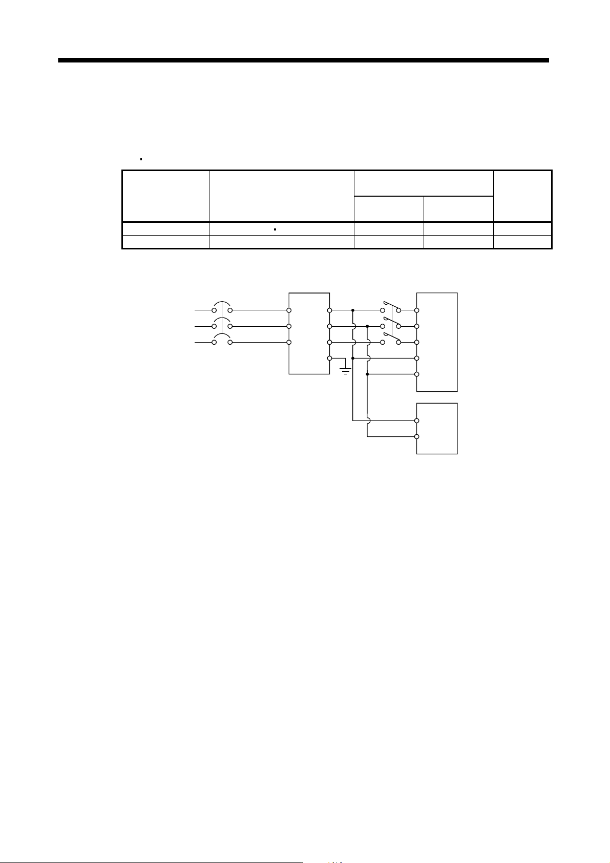
For compliance with the EMC directive of the EN Standard, it is recommended to use the following filter. Some
EMC filters are large in leakage current.
(1) Converter unit
Drive unit
Converter unit Drive unit
Recommended filter
(Soshin Electric)
Mass [kg]
Model
Leakage current
[mA]
MR-J3-CR55K MR-J3-DU30KB MR-J3-DU37KB HF3200A-UN 9 18
MR-J3-CR55K4 MR-J3-DU30KB4 to MR-J3-DU55KB4 TF3150C-TX 5.5 31
(2) Connection example
1
2
3
4
5
6
E
NFB
(Note)
Power supply
L
1
L
2
L3
L11
L
21
Converter unit
MC
Drive unit
L11
L
21
EMC filter
Note. For power supply specifications, refer to section 13.1.3.
13 - 89
13. SERVO AMPLIFIERS WITH A LARGE CAPACITY
(
30k TO 55kW
)
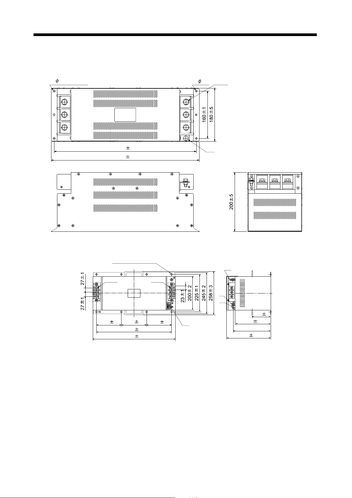
(3) Outline drawing
HF3200A-UN
[Unit: mm]
500 5
480 1
3- 6.5 3-M10
M8
3- 6.5 Length: 8
TF3150C-TX
[Unit: mm]
150 1 150 1 150 1
452 5
500 3
3-M8
3-M8
M4
M8
M4
M4
8-R 4.25 Length: 12
(for M8)
110 2
210 2
(227)
260 3
13 - 90
13. SERVO AMPLIFIERS WITH A LARGE CAPACITY
(
30k TO 55kW
)
13.9.10 FR-BU2-(H) Brake Unit
POINT
Use a 200V class brake unit and a resistor unit with a 200V class converter
unit, and a 400V class brake unit and a resistor unit with a 400V class
converter unit. Combination of different voltage class units cannot be used.
Install a brake unit and a resistor unit on a flat surface vertically. When the
unit is installed horizontally or diagonally, the heat dissipation effect
diminishes.
Temperature of the resistor unit case rises to higher than 100 . Keep cables
and flammable materials away from the case.
Ambient temperature condition of the brake unit is between 10 to 50 .
Note that the condition is different from the ambient temperature condition of
the converter unit (between 0
to 55 ).
Configure the circuit to shut down the power-supply with the alarm output of
the brake unit and the resistor unit under abnormal condition.
Use the brake unit with a combination indicated in (1) of this section.
For executing a continuous regenerative operation, use FR-RC-(H) power
regeneration converter or FR-CV-(H) power regeneration common converter.
When using the brake unit, set the parameters as shown below.
Setting value
Parameter No.PA01 of the MR-J3-CR55K(4) converter unit 00 (Initial value)
Parameter No.PA02 of the drive unit 00 (Initial value)
Connect the brake unit to the bus of the converter unit (L
and L of TE2-1) for use. As compared to the MR-
RB regenerative brake option, the brake unit can return larger power. Use the brake unit when the regenerative
brake option cannot provide sufficient regenerative brake capability.
When using the brake unit, always refer to the FR-BU2-(H) Brake Unit Instruction Manual.
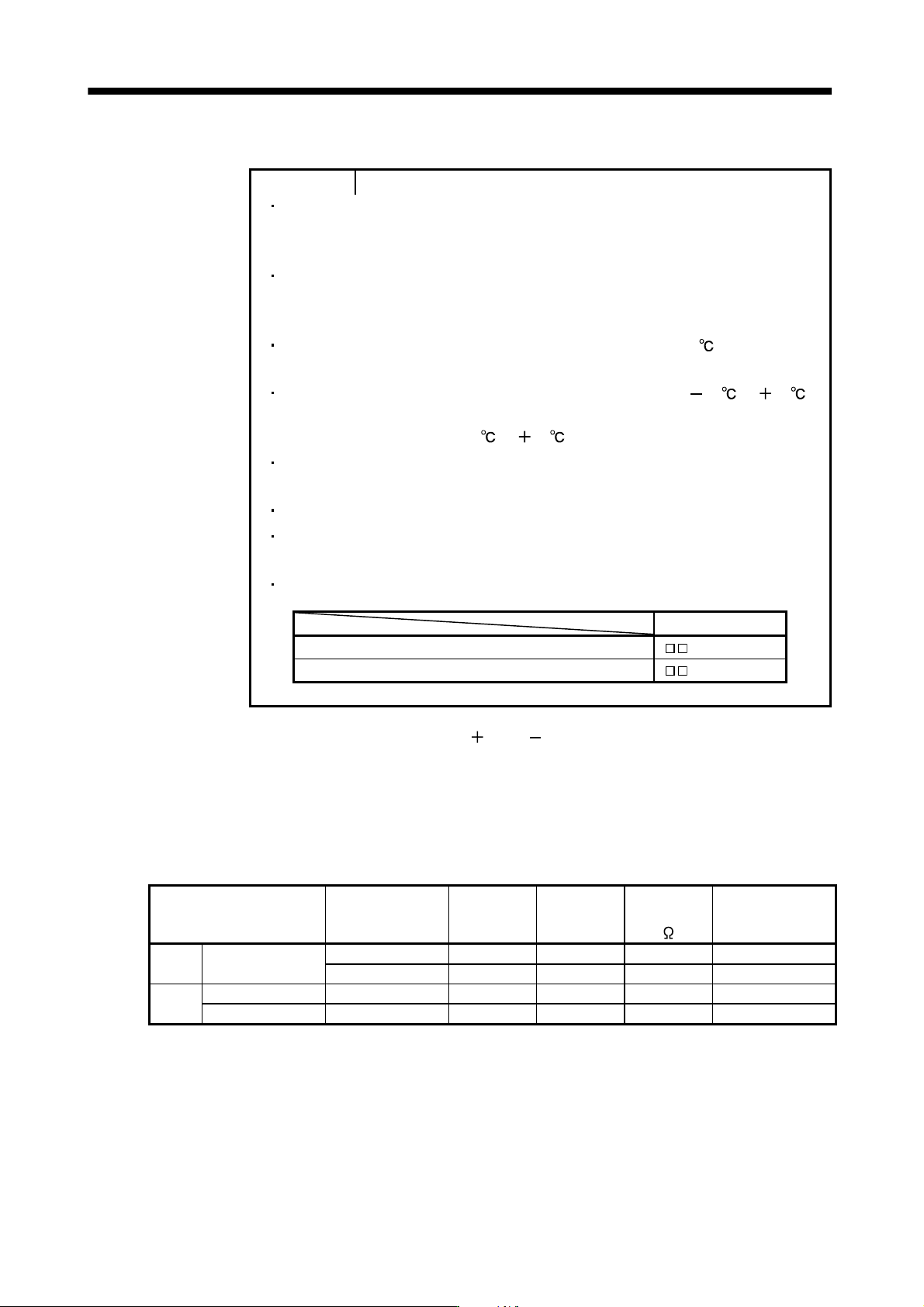
(1) Selection
Use a combination of converter unit, brake unit and resistor unit listed below.
Brake unit Resistor unit
Number of
connected
units
Permissible
continuous
power [kW]
Total
resistance
[
]
Applicable converter
unit
200V
class
FR-BU2-55K FR-BR-55K 2 (parallel) 7.82 1 MR-J3-CR55K
MT-BR5-55K 2 (parallel) 11.0 1 MR-J3-CR55K
400V
class
FR-BU2-H55K FR-BR-H55K 2 (parallel) 7.82 4 MR-J3-CR55K4
FR-BU2-H75K MT-BR5-H75K 2 (parallel) 15.0 3.25 MR-J3-CR55K4